
|
Home
| pfodApps/pfodDevices
| WebStringTemplates
| Java/J2EE
| Unix
| Torches
| Superannuation
| CRPS Treatment
|
| About
Us
|
|
|
pfodWeb Designer
|
by Matthew Ford 12th August 2026 (originally posted 17th July
2025)
© Forward Computing and Control Pty. Ltd. NSW
Australia
All rights reserved.
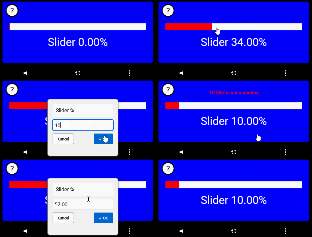
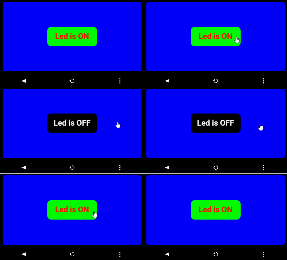
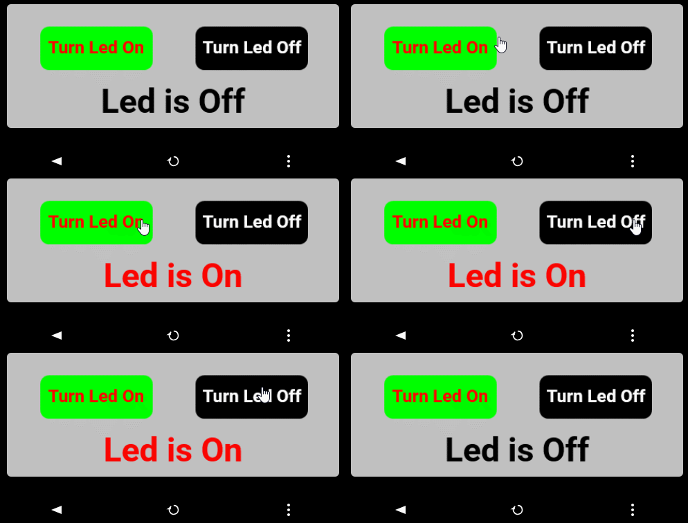
15th August 2026 –
Replaced with pfodWebDesigner
in pfodWeb.html. Revised tutorial
24th
October 2025 – V2.0.1
of pfodWebDesigner.zip
fixed display of nested dwgs and added Load Drawing Directory
9th
September 2025 – V1.1.3 of pfodWebDesigner.zip
now includes all the necessary npm packages to avoid downloading
possibly
compromised packages. pfodWebServer.zip
V1.1.3 now also includes all the necessary npm packages for hosting
pfodWeb on your computer. pfodWeb served from your microprocessor
does not use nodejs or any NPM packages. See How Safe
is pfodWeb, pfodWebServer and pfodWebDesigner below for the
details
pfodWeb.html is a single web page replacement for the paid Android app, pfodApp and the free pfodDesignerV3 and pfodGUIdesigner Android apps. pfodWeb open source and runs completely off-line. See the pfodWeb main page an overview of pfodWeb.html features and use.
To use pfodWeb.html for Charting
/ Data Logging of streaming CSV data, see Flexiable
Plotting with pfodWeb via Serial, BLE and HTTP
For menu design
and generation of complete code sketches to display ADC data, control
PWM, read / set digital I/O and plot and data log, see Control
and Data Display/Plotting for Arduino. Absolutely no Arduino or
Web coding needed.
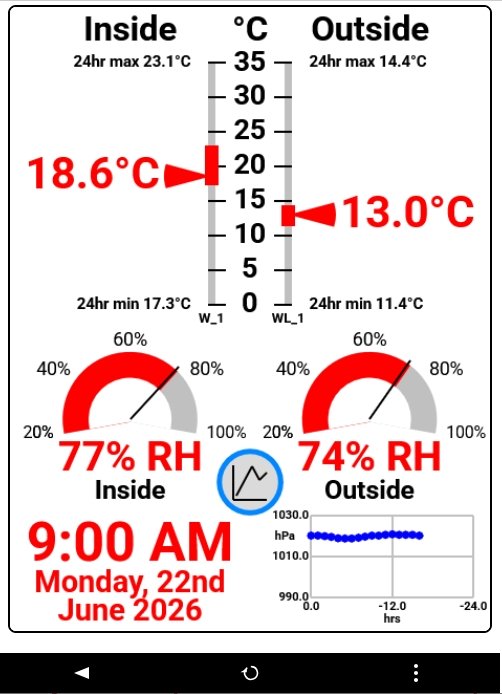
These tutorials cover the pfodWeb Dwg Designer which can be used to create interactive GUI's (drawings), like this BLE Weather Station, that can be added to a menu.
Often there is only a single drawing in the menu, but you can also
have multiple drawings and sub-menus. You have complete control over
the size, color, position and function of the controls you design
using pfodWeb Designer.
The messages that create the GUI are very
compact and can be served by any microprocessor that has a Serial,
Bluetooth Classic, Bluetooth Low Energy (BLE) or WiFi / HTTP
connection.
Introductory pfodWeb Designer
Drawing Tutorial – This
one. Covers using pfodWeb to create a simple press button example
that illustrates touchZone and touchAction.
Reusing
Controls with InsertDwg – Covers using insertDwg to insert
multiple basic controls into the main drawing.
touchActions
for Instant Feedback – Covers
using touchActions to give instant feedback in a slider
control.
TouchActionInput
for text/number entry – Covers using touchActionInput to
input text / numbers to your micro
Building
Reusable Controls – Covers
building a re-usable popup help button component.
pfodWeb.html is free and open source. If you want to support this work, purchase the Android pfodApp which will work with the same code developed here
See the
Introductory Tutorial for
the parts list and the Quick
Start instructions.
Arduino Mega or higher recommended for
these tutorials, although an Arduino UNO will work for the examples
on this page.
The complete source code for pfodWeb.html is
available in pfodWeb_src.zip
and on Github.
Install Arduino
IDE V2. Install the latest pfodParser library from the library
manager OR the pfodParser.zip
Upload the Examples → pfodParser → pfodWeb →
demoScreens_serial.ino
Open
…Arduino/libraries/pfodParser/pfodWeb/pfodWeb.html in
your browser.
Choose the Designer connection
Choose your
target board. For the first Hello World example an Arduino
UNO is
sufficient
Click Open
Designer to
show the Designer's Main Menu.
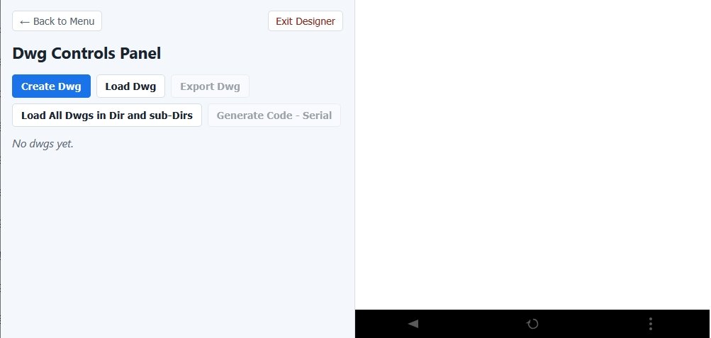
Click on the Create/Edit Dwg button to open the Drawing Designer.
There will be three (3) introductory examples in this
tutorial.
Hello World, a simple dwg displaying a text label.
Hello World Counter, a dwg with auto refresh and
updates.
LedOnOff, a on/off button to control the board led. Shown
at the top of this page. This example has an interactive / updateable
button that responds instantly to mouse touches and updates with the
current led state.
The two button example, pfodWeb_LedOnOff, will be covered in a later tutorial, Reusing Controls with InsertDwg.
This section covers loading an existing design, editing it and exporting the Arduino code that implements it.
This simple example will open the HelloWorld.pfodDwg_json and edit it. Download the HelloWorld.pfodDwg_json, click on Load Dwg and select it from your downloads folder.
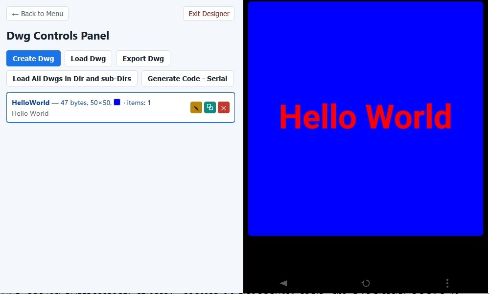
Then click on the Edit Drawing pencil symbol, the first of the right hand trio of symbols, to open the edit screen for this drawing.
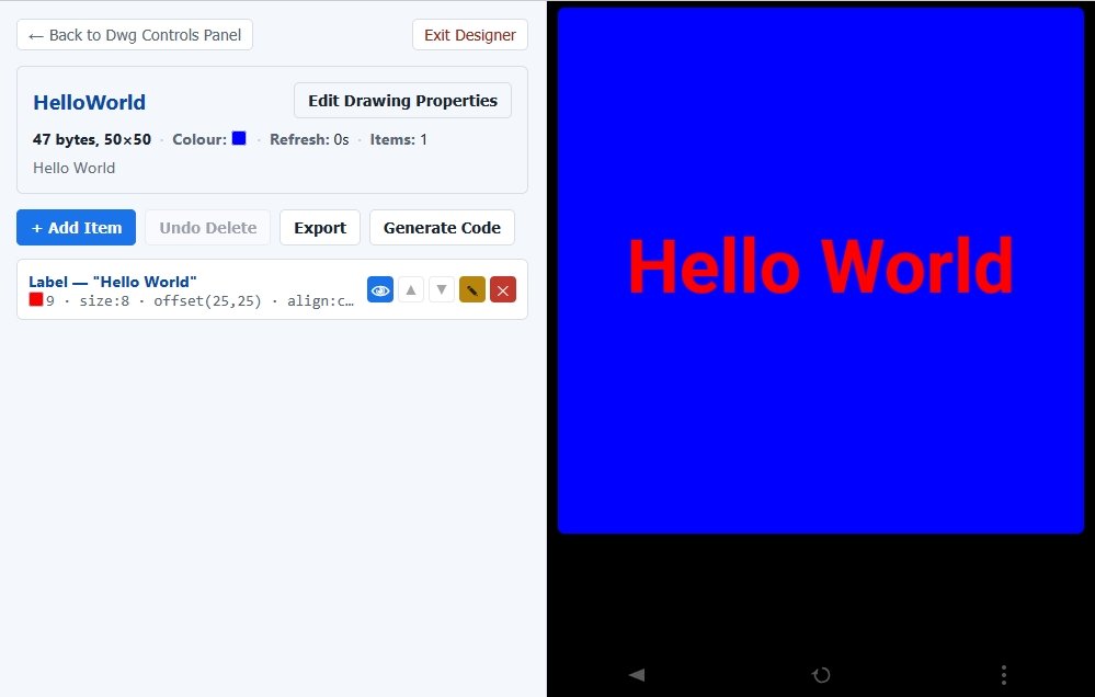
From here you can use Edit Drawing Properties to change the size of the canvas, the background colour, the auto refresh interval.
You can also edit the Text item, Hello World. Press the eye button
on the right, to flash the item on/off so you can identify the item
within the drawing.
Click the pencil icon to open the Edit Item
screen this this text item.
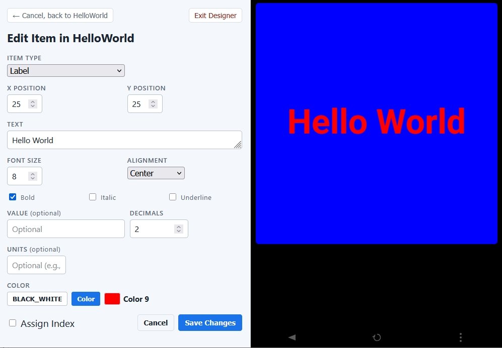
Here you can change the text, size, alignment, style and color. You can even change the drawing item from a text item to some other like a line, rectange, etc. Cancel if you don't want to save those changes.
The Black_White color selection makes the drawing item either Black or White depending on which has the highest contrast against the drawing's background color. This setting is particularly useful to keep text visible when that drawing is inserted into another drawing. Inserted drawings do not bring their background color with them, only their drawing items, which are merged with the main drawing. See the Reusing Controls with InsertDwg tutorial for more details.
Each Save Changes automatically updates the drawing in the browser's local storage, so you won't lose any edits when you Exit Designer, close the pfodWeb.html web page or close the browser.
Either Save Changes or Cancel to go back to the Hello World drawing. From there you can Export the drawing ...pfodDwg_json file for reloading later or Generate Code to produce a complete sketch that will connect via Serial to display this drawing in pfodWeb.html. The generated zip file contains the .ino sketch, the supporting .cpp/.h files and the, in a sub-directory, the HelloWorld.pfodDwg_json file of the dwg used to generate the sketch.
Click Generate Code to produce the HelloWorld_serial.zip
Unzip that file to your Arduino sketch directory.
Open the
HelloWorld_serial.ino in the Arduino IDE and upload it to any Arduino
board, UNO or higher.
Exit Designer or reload the pfodWeb.html page and select the Serial connection and Connect to display the Hello World. See pfodWeb Quick Start for more details

The pfodWeb.html implements the pfod menu caching. This caches the
menu/drawing data with its version, so that when requesting
updates/refreshes only the changes are sent, not the whole
menu/drawing. To see the pfod messages, open the Raw Message View
from the bottom right hand … menu button.
If pfodWeb does
not seem to displaying your changes, you can either change the
version string in the .ino file OR more simply click the Clear
Menu Cache button at the bottom of the Connection screen and then
re-connect
The pfodParser library V3.65.1+ includes the HelloWorld_serial example. This example consists of the main sketch, HelloWorld_serial.ino, the pfodMainMenu (.cpp/.h), the pfodMainDrawing (.cpp/.h) and the drawing (Dwg_xxx) files the main drawing needs. The .ino sketch file handles setting up the connection, either Serial, BLE or WiFi, depending on your board. The pfodMainMenu handles serving the main pfod menu in response to the {.} request. In this pfodWeb framework, the main menu consists of just a drawing. The pfodWeb (or pfodApp if using the WiFi connection) then requests the main drawing and any inserted drawings to finally display the user interface.
When you modify your drawing, you only need to replace/update the
Dwg_xxx files. The main sketch .ino, the pfodMainMenu and the
pfodMainDrawing files can remain the same as long as the name of the
main drawing is the same.
See the pfodSpecification.pdf,
page 42 onwards, for all the details of pfod drawing items.
This example will modify the Hello World to add a loop counter and a 5sec auto-refresh which will request the current value every 5 seconds and display it.
Open the pfodWeb Dwg Designer, load the HelloWorld.pfodDwg_json
(if necessary) and then uses Copy button (center of the three
right side buttons) to make a copy called HelloWorld_1.
Open
it for editing and click on Edit Drawing Properties
Change the drawing name to HelloWorldCounter, update the description and set the Refresh Rate to 5 secs and Save Changes.
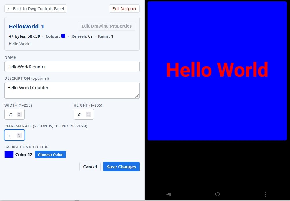
An auto-refresh interval can be set on the main drawing as well as on inserted dwgs. Setting a refresh interval on the main drawing (or the menu that holds it) causes the drawing and any inserted dwgs to be re-requested at that interval. The pfodWeb Dwg Designer specifies the refresh in seconds. The pfod Arduino code uses ms.
To set the refresh interval, click Edit Canvas Properties and set 5 sec refresh.
To add the Counter, click the Add Item and choose Label
from the Item Type drop down
list.
Label lets you send
a leading and trailing text with an embedded floating point number
for display, or just plain text like Hello World. Value
is similar but accepts integers and
transforms (maps) them for display.
Set the Text as Count:
with a trailing space and set the
Units as loops with a
leading space. Set the initial Value as 0.
Value needs to be set to display the Units.
Set the Decimals as 0
and Alignment as Center.
Position the text using the X and Y Position settings.
X and Y positions (and sizes) can be
floating point numbers for precise positioning.
Font Size is an
integer and is relative to the webpage / screen size. Increasing the
number by 6 doubles the font size, decreasing by 6 (e.g. -6) halves
it.
Most Important. Tick the Assign Index button. Only indexed drawing items can be updated. The index is the variable name holding the unique reference to the item. In this case the counter label.
The default color is BLACK_WHITE, which ever gives the best contrast, choose Color if you want to specify a particular color for the text.
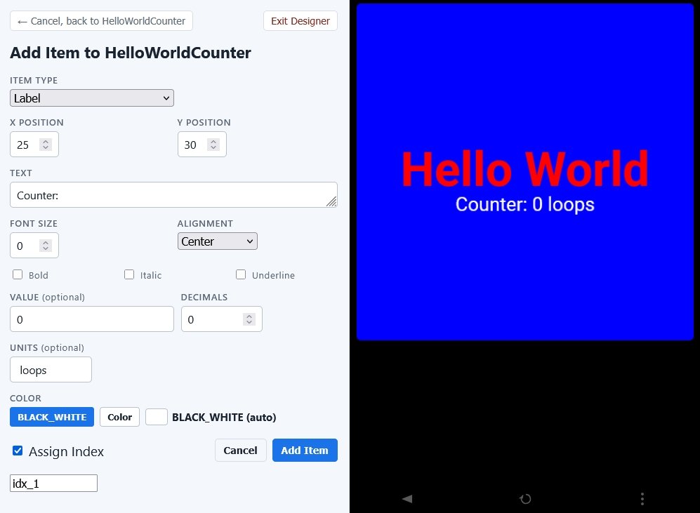
Click Add Item to go back to the Edit Drawing page.
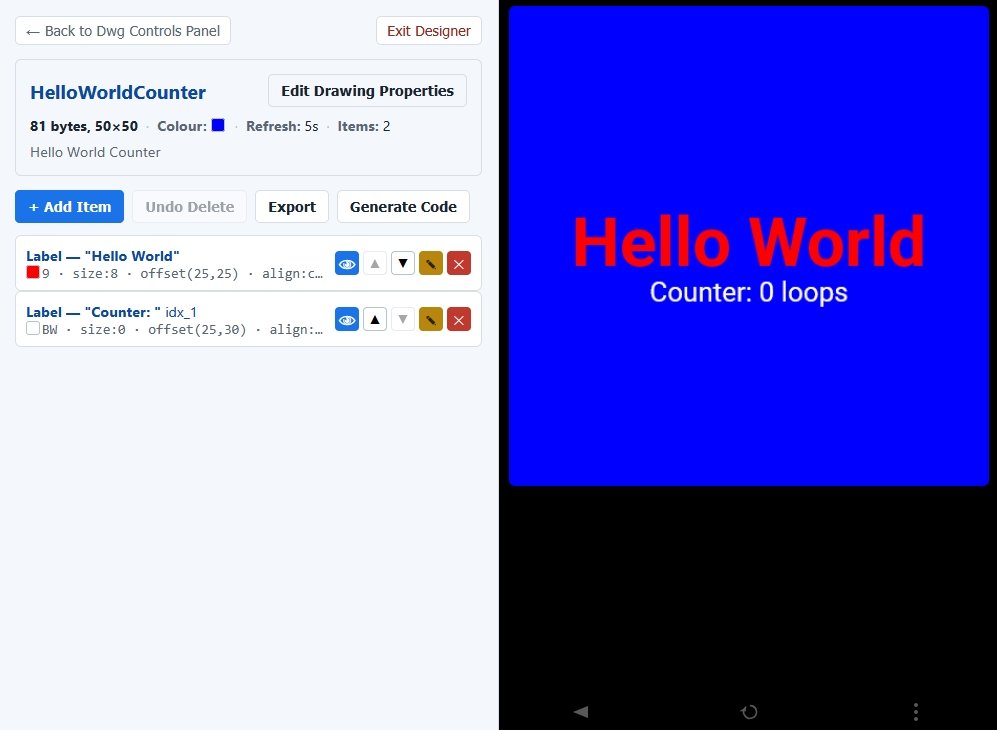
Click Generate Code to produce the HelloWorldCounter_serial.zip
Only indexed drawing items can be updated without re-sending the entire drawing. The code generator puts all the index items in the virtual void Dwg_HelloWorldCounter::sendIndexedItems() method, so that is the method you need to put the changes in. You can either modify that method directly, which will be done here, OR you can sub-class the Dwg_HelloWorldCounter class and override the sendIndexedItems() method to include your changes. Sub-classing is recommended for more complex logic to improve the separation of the logic from the display.
Save the sketch as HWCounter with these changes to the Dwg_HelloWorldCounter.cpp file. Here the dummy 0 in .value( ) is replaced by the real loopCounter.
extern unsigned long loopCounter; // set in .ino loop()

void Dwg_HelloWorldCounter::sendIndexedItems() {
  dwgsPtr->label().idx(idx_1).color(dwgsPtr->BLACK_WHITE).text("Counter: ").offset(25,30).center().units(" loops").decimals(0).value(loopCounter).send();
}
In the HWCounter.ino add
unsigned long loopCounter = 0;
void loop() {
 loopCounter++;
 handle_mainMenu(parser); // handle i/o via this parser
}
Then when you upload this code you will see the display update every 5sec with the current loop counter value. The completed sketch is in HWCounter_serial.zip
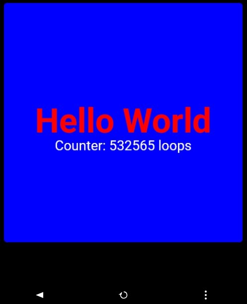
You can use the center refresh button to force a refresh before the 5 sec interval times out.
The LedOnOff example creates a new drawing and adds a button to turn the microprocessor's led on and off. It uses a touchZone to make part of the web page responsive to mouse actions and adds a touchAction which is triggered immediately the mouse action is detected to indicate the button has been clicked. The drawing update changes the button's text and color to indicate the current state of the led, on or off.
Open the pfodWeb Dwg Designer and click on Create Drawing. Call it LedOnOff with dimensions 50 x 25, background color Blue (12) with a 4 second refresh.
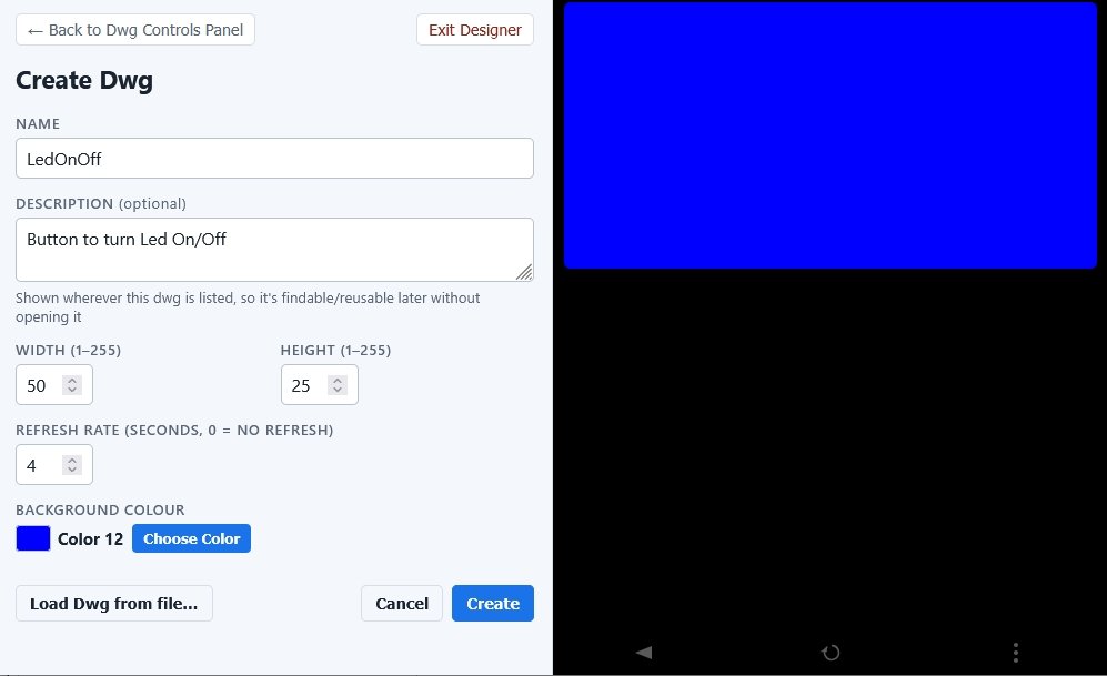
You can choose any convenient dimensions from 1 to 255 for the drawing width and height. When the drawing is displayed it will be scaled to fit in the pfodWeb page / pfodApp screen. It is only the ratio of the width to the height that is important. Later tutorials will cover choosing particular dimensions to set the mouse position resolution in touchZones.
Edit the drawing to add an indexed rectangle for the button and
and indexed label indicating the Led's state, on or off.
Note:
When adding the label, click Assign Index first and then position it.
Un-indexed items are drawn first in order and then overlaid by
indexed items in their listed order. So because the rectangle is
indexed it will cover an un-indexed label in the same position.
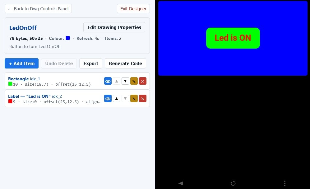
Important: Note that both the button rectangle and the label have Use Index ticked, as they will be both be updated when the button is clicked and when the led state is updated.
Add a touchZone over the button. The dotted outline indicates the touchZone. This outline will not be visible in pfodWeb / pfodApp unless Debug mode is used. However pfodWeb Web Designer will display its outline while editing.
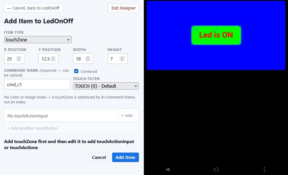
Click Add Item to add the touchZone and then edit it to add
the touchActions.
touchActions will trigger
immediately the mouse triggers the touchZone.
Click on the Add another touchAction, select the indexed Rectangle. You can use the eye icon to flash that dwg item.
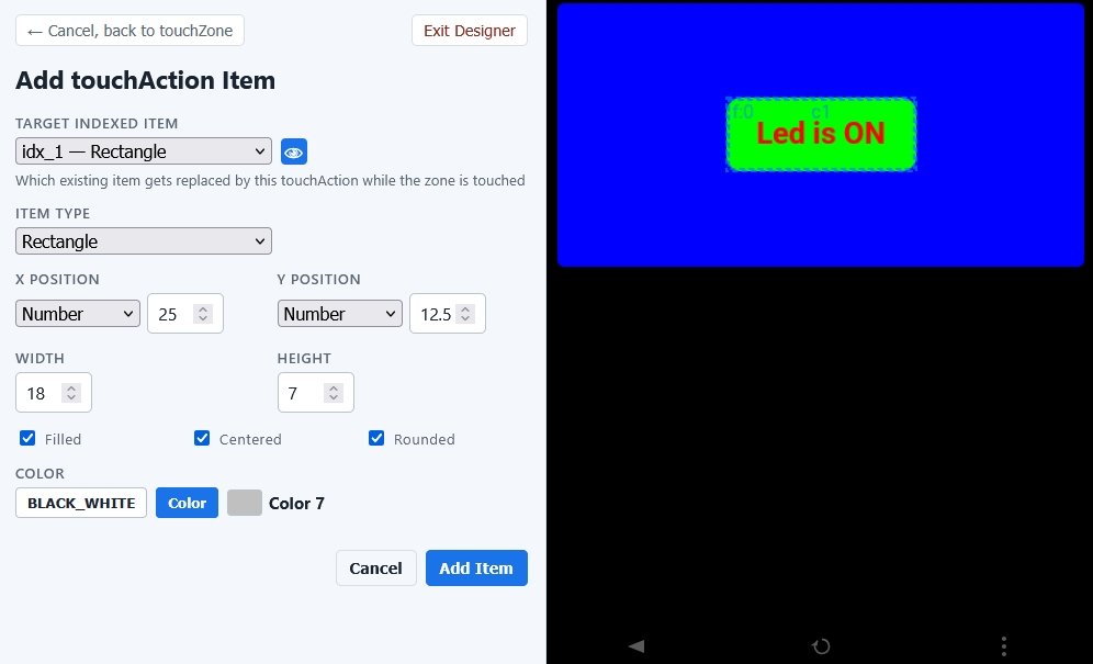
When the touchZone is triggered, you
can replace this rectangle with any other drawing item. In this case
just a Grey rectangle of the same size and position, to give the user
instant feedback that the button has been clicked with out waiting
for
Press the Led is ON button in the preview to see the
replacement happen.
Click Add Item to add that touchAction
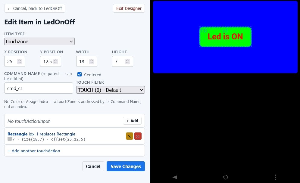
Click Save Changes to go back to the Edit Drawing screen.
Again you can click in the touchZone, in the preview, to trigger the
touchActions.
Click Generate Code to write the
LedOnOff_serial.zip
file.
Unzip it to your Arduino sketch directory.
The completed sketch files, with these modifications, are in LedOnOff.zip
In this example, instead of modifying the Dwg_LedOnOff.cpp file directly, it will be sub-classed to implement the LED control and display update. Two new files, LedControls.cpp and LedControls.h, sub-class Dwg_LedOnOff.cpp, add the Led control functions and state and overwrites the Dwg_LedOnOff_cmd_c1() method, which gets called when the touchZone is clicked, and also overwrites the sendIndexedItems() method to keep the display in sync with the Led state.
The LedControls.cpp / .h file for the changes. LedControls.cpp defines
Dwg_LedOnOff& get_dwg_LedOnOff() {
 return ledControls;
}
That replaces the weak get_dwg_LedOnOff() method in Dwg_LedOnOff and returns the sub-class instance to be used instead of the dwg_LedOnOff. Virtual method definitions ensure the LedControl method are called instead of the LedOnOff methods. As well as the methods controlling the board led, LedControl overrides two dwg methods, Dwg_LedOnOff_cmd_c1() which gets called when the button is clicked and sendIndexedItems() which is called to update the display when responding to the button click.
The Dwg_LedOnOff_cmd_c1() code is
bool LedControls::Dwg_LedOnOff_cmd_c1(int row, int col, uint8_t touchType, const byte* editedText) {
 (void)row; (void)col; (void)touchType; (void)editedText; // suppress warnings
 if (isLedOn()) {  // toggle the led
  turnLedOff();
 } else {
  turnLedOn();
 }
 sendUpdate();  // sendUpdate from here
 return true; // handled here, return true, if only this dwg needs updating
}
On each button click it toggle the led state and then sends the dwg update to update the button color and text. sendUpdate() in Dwg_LedOnOff, just starts the drawing update and then calls sendIndexedItems() to update the indexed dwg items. LedControls overrides sendIndexedItems() to send the appropiate button color and text depending on the led state.
void LedControls::sendIndexedItems() {
 if (ledIsOn) {
  Dwg_LedOnOff::sendIndexedItems(); // call super class sendIndexedItems() which shows led ON button color and text
 } else {  // BLACK button, WHITE text -- Led is OFF
  dwgsPtr->rectangle().filled().centered().rounded().idx(idx_1).color(dwgsPtr->BLACK).size(18, 7).offset(25, 12.5).send();
  dwgsPtr->label().idx(idx_2).color(dwgsPtr->WHITE).text("Led is OFF").bold().offset(25, 12.5).center().decimals(2).send();
 }
}
It leverages the default, Led is On, state that is defined in Dwg_LedOnOff and add the OFF state code.
The easiest way to create the update code is to edit the drawing items to the colour and text you want for led OFF and then generate the new drawing files and pick up the updated sendIndexedItems() code to use for Led OFF
The result is the animated one button GUI at the top of this page. As you select the button it flashes a GREY color change and sends a command to your microprocessor to change the LED. When the microprocessor responds, its message sets the button's new color and the new text. It also calls for an update every 5sec to pick up any outside changes to the Led state.
pfodWeb.html is pure html / js and does not use any external packages or downloads. You can run pfodWeb.html completely off-line with no internet connection. The complete source code for pfodWeb.html is available in pfodWeb_src.zip and on Github. pfodWeb.html runs in any browser. If your browser does not support Serial and/or BLE connections natively, you can used the Rust based pfodProxy to provide that support. See pfodWeb_startup.html
This page covered using pfodWeb Dwg Designer to design interactive
GUI's that can be displayed by either the pfodWeb.html browser page
or pfodApp.
This
tutorial included three simple examples, HelloWorld,
HelloWorldCounter, which displayed the current loop count, and
LedOnOff which used a touchZone and touchActions to control an UNO
onboard led.
The next tutorial, Reusing Controls with InsertDwg covers using insertDwg to insert multiple basic controls into the main drawing.
AndroidTM is a trademark of Google Inc. For use of the Arduino name see http://arduino.cc/en/Main/FAQ
The General Purpose Android/Arduino Control App.
pfodDevice™ and pfodApp™ are trade marks of Forward Computing and Control Pty. Ltd.

Contact Forward Computing and Control by
©Copyright 1996-2024 Forward Computing and Control Pty. Ltd.
ACN 003 669 994