
|
Home
| pfodApps/pfodDevices
| WebStringTemplates
| Java/J2EE
| Unix
| Torches
| Superannuation
| CRPS Treatment
|
| About
Us
|
|
|
pfodWeb
|
by Matthew Ford 22nd October 2025 (originally posted 4th August
2025)
© Forward Computing and Control Pty. Ltd. NSW
Australia
All rights reserved.

This is the third tutorial on using pfodWeb Designer to create
interactive and responsive GUI for pfodApp and the free, open source,
pfodWeb.
This tutorial will cover touchActions in more detail and
how the message they send includes the x,y point. It also covers
using that data to give uses instant feedback of mouse position on a
slider position without having to wait for the pfodDevice to respond.
Your micro serves all the necessary code to run the web page
controls. No third party js libraries or internet access is needed.
pfodWeb
is a free web based partial
replacement for the paid Android app, pfodApp.
pfodWeb runs in a browser and connects to your Arduino board via
either Serial or BLE or HTTP. Using Serial you can connect to any
Arduino board and display the interactive controls it serves. pfodWeb
runs competely off-line. No internet connection is needed. Just
install the pfodParser library and open the index.html in the pfodWeb
sub-directory of the pfodParser library. The interactive controls are
completely defined by the code (generated by pfodWebDesigner) in your
Arduino. Very compact pfod
messages are used to send the controls and receive the user's
commands.
If your Arduino board supports HTTP and has a file
system of 200Kb, then you can load the all pfodWeb files onto your
microprocessor and serve them directly from there.
pfodWebDesigner is a free web based replacement for the free Android app, pfodGUIdesigner. pfodWebDesigner allows you to design interactive and responsive user interfaces for your microprocessor. pfodWebDesigner generates Arduino code that works with all pfodDevices that connect via Serial, Bluetooth, BLE, SMS and WiFi, not just those that have WiFi support. See how to install pfodWebDesigner and Using pfodWeb Designer to Create GUI's. Individual pfodWebDesigner controls are stored as JSON files which you can duplicate, modify and reuse in other designs. Each reused control can be individually scaled and positioned in the final design.
Introductory
pfodWebDesigner Tutorial – Covers setting up
the pfodWeb Designer local server and install the pfodWeb support on
an ESP32. A simple press button example illustrates touchZone and
touchAction.
Reuse
Controls with insertDwg – Covers copying dwgs
and using insertDwg to insert multiple copies into the main
drawing.
touchActions for Instant Feedback –
This one. Covers using touchActions to give instant feedback in a
slider control.
TouchActionInput
for text/number entry – Covers using touchActionInput to
input text / numbers to your micro
Building
Reusable Controls – Covers
building a re-usable popup help button component.
pfodWeb is free and open source. If you want to support this work,
purchase the Android pfodApp
which will work with the same code developed here and which provides
more features such as charting and data logging.
See the free
pfodDesigner
Android app for creating menus and charts for pfodApp.
See the Introductory Tutorial for the parts list and the Installation instructions. Physical parts consist of just an Arduino board, e.g. Dfrobot ESP32 board or other Arduino board. (An UNO does not have enough memory to run these examples)
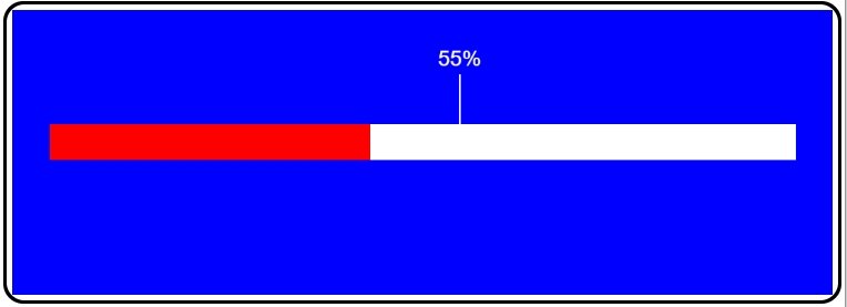
This tutorial creates a simple slider, shown above, which allows the user to touch or drag the slider and see what value will be set, before the command is sent to the microprocessor (pfodDevice). It will also cover the touchZone messages in more detail and how to extract the position in the touchZone that the user touched and the use of BLACK_WHITE for item color.
Open pfodWebDesigner and create a dwg called BasicSlider
with dimensions 110 x 40 and background color 12 (BLUE).
You can
reuse this drawing later in other GUI's by using insertDwg to add it
as was covered in the previous tutorial, Reuse
Controls with insertDwg
This dwg will have multiple items added so start with a pushZero
xOffset 5, yOffset 0, scale 1, to reposition the (0,0) for the
following items.
Add a white filled rectangle 100 x 5
xOffset 0, yOffset 16
Add a red filled rectangle 10 x 5
xOffset 0, yOffset 16 and Use Index. This will be updated by
your Arduino code to show the current slider position.
Add a touchZone 100 x 5 xOffset 0, yOffset 16 with touch filter: DOWN_DRAG_UP.

The touchZone with filter DOWN_DRAG_UP will respond to mouse down and drag but only send one message on mouse UP. The message sent will contain the main drawing load command, the touchZone cmd, the mouse location in touchZone co-ordinates and filter setting that triggered the message. E.g.
{A~c1`47`5`256}
where (47,3) is the x,y position in the touchZone and 256 is the filter value for DOWN_DRAG_UP.
In your Arduino code, the pfodParser automatically parses these commands and makes the values available via the methods, getTouchedX() and getTouchedY() and getTouchType(). There are also utility methods like isTouch(), isDrag(), isUp() etc.
The touchZone mouse co-ordinates start at (0,0) top left hand corner of the touchZone and extend to (width,height) at the bottom right hand corner. These are independent of the position and scaling of the touchZone in the final drawing. That is this touchZone (100 x 5) will always return a mouse x position between 0 and 100 regardless of how the slider is scaled and positioned when inserted in the main drawing.
These mouse co-ordinates are always integers, which simplifies your Arduino code, so the mouse resolution depends on the size of the touchZone. While the maximum size of a dwg ins 255 x 255, the touchZone can be much larger and then scaled down to display on the dwg. This makes the maximum resolution for the mouse position only limited by the screen pixels.
In practice, the touchZone should be sized for a relatively coarse resolution so that the user does not have to exercise fine mouse control to make a selection. For this slider a touchZone width of 100 allows for 1% slider settings.
Each touchZone is automatically enlarged slightly so that
i) a
mouse click near the edge of a button or slider will still trigger it
and
ii) so that very small touchZones will still have a clickable
size.
This enlargement does not depend on the touchZone's scaled dimensions but is set by the current screen size and does not effect the mouse position returned by the touchZone which is always limited to the touchZone's Width and Height. If touchZones overlap, a best fit algorithm is used to determine which one is triggered. There is also, an advanced, priority setting that can be used to force one touchZone to take precedence over another. See the pfodSpecification.pfd for the details.
Go back to the control panel and use the Arduino Export to export the Slider Arduino code Slider_serial.zip
Open the sketch in Arduino and the slider control files to keep
track of the position.
SliderControls.h
#ifndef SLIDER_CONTROLS_H
#define SLIDER_CONTROLS_H
void setPosition(float pos);
float getPosition();
#endif
and SliderControl.cpp
#include "SliderControls.h"

float position;

void setPosition(float pos) {
 position = pos;
}

float getPosition() {
 return position;
}
Edit the Dwg_Slider.cpp file to read the slider position from parserPtr->getTouchedCol(); and set the length (width) of the slider ribbon from getPosition()
#include "SliderControls.h"
. . .
bool Dwg_Slider::processDwgCmds() {
if (!(*(parserPtr->getDwgCmd()))) { // ==> getDwgCmd returned pointer to empty string
return false; // not dwg cmd, not handled
}
if (parserPtr->dwgCmdEquals(cmd_c1)) { // handle touchZone cmd_c1
setPosition(parserPtr->getTouchedCol());
sendUpdate();
return true;
}
return false; // not handled
}
void Dwg_Slider::sendIndexedItems() {
dwgsPtr->rectangle().filled().idx(idx_1).color(dwgsPtr->RED).size(getPosition(),5).offset(0,16).send();
}
The completed sketch is in BasicSlider_serial.zip Uploading this will display the slider. Clicking in it will update the position and the ribbon.
Note that nothing updates until you release the mouse
button.
There are no touchActions specified so nothing
changes as you drag the mouse in the touchZone.

The basic slider only updates the red rectangle when the pfodDevice (your microprocessor) responds to the mouse UP message. Using touchActions you can show the user immediate feedback as they move the mouse. In touchActions, the special values COL and ROW, are replace, on the fly, by the current mouse position in the co-ordinates to the touchZone. Note: these values are the same as the ones sent in the touch message and are integers in the touchZone co-ordinates.
This section of the tutorial will add touch actions using COL to show where along the slider the mouse is and what % the slider will be set to when the mouse UP sends the touch message. These updates happen immediately in the drawing itself and do not require any messages to or from your microprocessor.
Reopen the Slider.json dwg .json file (which is in the json sub-directory of the generated sketch) in the pfodWeb Designer.
Before editing the touchZone actions, via the Show Details button, two index place holders need to be added. These place holders will be updated/replaced with the touchActions to update the position indicator and % value.
Using on Add New Item and add two Index Placeholder items. These index items capture the current pushZero settings so that when they are replaced by the touchActions the touchActions have the correct (0,0) location and scale.
Then click on the touchZone Show Details button to expose the Add touchZoneInput and Add touchAction buttons.

Click on the Add touchAction button and then on the next page click on the Add touchAction Item button

Holding down the idx_1 rectangle Show button will hide the red rectangle so you can check which item the touchAction will replace. Index items are not visible so they do not have a Show button.
Click the Replace on Touch button for idx_2 to open the Add touchAction Item page. Clicking in the touchZone will trigger it (depending on the filter setting) and replace idx_2 with the default line item.
Edit the Line item to change the X Offset to COL
(Touch Column) and the Y Offset to 16 and the X to
0 and Y to -7 and color 15 (WHITE), so that when the
touchZone is triggered, a line from (col,16) to (col+0,16-7) will be
drawn to replace idx_2
Move the mouse down in the touchZone
to test the result, as shown below. The white line only appears when
the mouse is down in the touchZone and moves left and right
with the mouse. Otherwise the dwg reverts to the invisible idx_2

Add Item to accept this touchAction.
On the touchActions Items page, click Add touchAction Item again to and select Replace on Touch for idx_3 to add a touchAction for that index.
Click the drop down list of items and choose Value. Choose
COL for the X Position and 7 for the Y Position and
Alignment Center and Color 15 (WHITE)
Mouse down in the
touchZone will show the white line and now the text Value: 0.50
To show the current mouse
position on the slider, in the Value Scaling Parameters
choose COL for the Integer
Value and set the Display Max to
100 and Decimals to
0
Set the Units to
% and delete the Value:
text from the Prefix
Text: Then when you mouse down
and drag in the touchZone you
will see the current % setting

Add Item to accept these edits

Finally, Accept Changes to add these touchActions to the touchZone.
Go back to the Control Panel and export the just the drawings Arduino code with the Arduino Export button to produce Dwg_Slider.zip and merge these changes into your Slider_serial sketch.
Note: If the Arduino linker complains of duplicate symbols, it has not cleared out the old cached compiled files. Change the board to a different one (any one) and start a compile. Then cancel the compile and change back to the correct board and re-compile.
Uploading this sketch now shows the slider percent indicator as the mouse is dragged. The completed sketch is in Slider_serial.zip
You can also add a label to display the current slider setting.
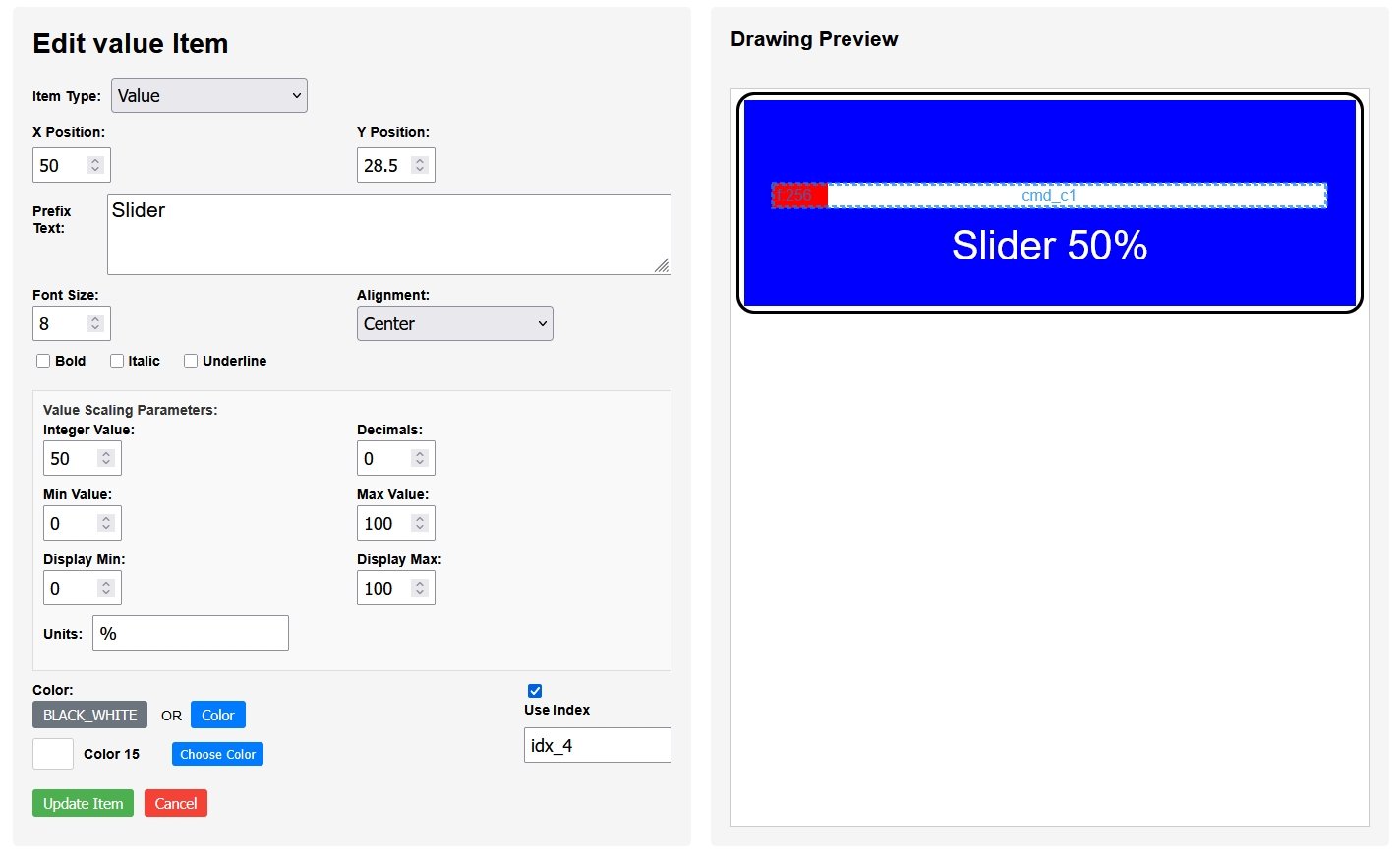
Open the
Slider_serial.json file again in pfodWebDesigner and add a Value
Item, indexed. Value Items differ from Labels in that they map the
Integer Value before displaying it.
The mapping is from
(minValue,maxValue) to (display minValue, display max Value). In this
instance the mapping is from 0 – 100 the size of the slider
touchZone to 0 – 100 %
Export the Ardino Drawings Only code again and merge it with the existing sketch.
In Dwg_Slider::sendIndexedItems() replace the intValue(50) with the current position, inValue(getPosition());
void Dwg_Slider::sendIndexedItems() {
  dwgsPtr->rectangle().filled().idx(idx_1).color(dwgsPtr->RED).size(getPosition(),5).offset(0,16).send();
  dwgsPtr->label().idx(idx_4).color(dwgsPtr->WHITE).text("Slider ").fontSize(8).offset(50,28.5).center().intValue(getPosition()).units("%").maxValue(100).minValue(0).displayMax(100).displayMin(0).decimals(0).send();
}
The
completed sketch is in SliderWithValue_serial.zip.
Uploading that gives the user interface shown at the top of the
tutorial
This page covered using touchActions to give the user immediate feedback. It covered more detail the message that a touchZone sends when triggered. The message includes the x,y point in touchZone co-ordinates which do not change with the position and scaling of the touchZone in the final drawing.
AndroidTM is a trademark of Google Inc. For use of the Arduino name see http://arduino.cc/en/Main/FAQ
The General Purpose Android/Arduino Control App.
pfodDevice™ and pfodApp™ are trade marks of Forward Computing and Control Pty. Ltd.

Contact Forward Computing and Control by
©Copyright 1996-2024 Forward Computing and Control Pty. Ltd.
ACN 003 669 994