
|
Home
| pfodApps/pfodDevices
| WebStringTemplates
| Java/J2EE
| Unix
| Torches
| Superannuation
|
| About
Us
|
|
|
How to Display/Plot Arduino Data on Android
|
by Matthew Ford 29th October 2018
(originally posted 12th June 2016)
© Forward
Computing and Control Pty. Ltd. NSW Australia
All rights reserved.


The project is suitable for complete beginners. No coding experience is required. Once you have finished this tutorial you will be able to design whatever menus you need to display, plot and log Arduino Data, Analog readings and Digital Inputs, and control Arduino outputs, PWM outputs and Digital Outputs. In particular this tutorial will show you how to display, plot and log an Analog reading and display the state of a Digital input and control a PWM output and pulse a Digital Output.
To actually switch something on and off see How to Add Relays to Arduino and Simple Home Automation for Beginners. There are also more pfodDesigner tutorials and another tutorial Data Logging and Plotting available and there is also a new pfodDesigner tutorial on plotting against date/time using only the Arduino millis() function, Arduino Date and Time using millis() and pfodApp
Absolutely NO CODING IS REQUIRED for this tutorial. No Arduino coding is required, the pfodDesignerV3 generates all the code you need. No Android coding is required, the general purpose pfodApp displays the menus and data and plots and logs the data and handles user inputs. However this tutorial only covers some the screens and display options available in pfodApp. Check out the complete pfodSpecification for all the details.
pfodApp runs on Android mobiles, V2.1 onwards and can connect using Bluetooth Classic, Bluetooth Low Energy (BLE), Wifi and SMS.
On the Arduino side, the pfodDesignerV3 Vgenerates code for Arduino 101 (BLE), UNO and compatibles (MEGA 2650 etc.), ESP8266 boards, ESP32 boards, Adafruit Feather M0 LoRA/Radio boards, Teensy/Feather LoRa Wing stacks, RedBear BLE, RFduino, and a variety of Ethernet, Bluetooth, Bluetooth LE, WiFi and SMS shields.
This project is suitable for complete beginners, but you need complete a few tasks before you start. You need to first set up the Arduino IDE, install pfodDesignerV3 and make sure you can transfer the final sketch (code file), that pfodDesignerV3 produces, from your mobile to your computer.
a) Install the Arduino IDE for
your computer's operating system from Getting
Started with Arduino and work through the example of compiling
and running the Blink example.
b) Install the free pfodDesignerV3
app on your Android mobile.
c) Check that you are able to
transfer files from your mobile to your computer either via a USB
cable or a file transfer app such as WiFi
File Transfer. See
pfodAppForAndroidGettingStarted.pdf
for more details.
The pfodDesignerV3 is free so you can do most of this tutorial with just that pfodDesignerV3 on your Android mobile. But if you want to actually display/plot some data or switch something on/off you will need to buy an Arduino compatible board and pfodApp.
This tutorial will use an Arduino 101 / Genuino 101 as the example board, it has built-in Bluetooth LE communication. But you can use a variety of other hardware. See this page for other BLE boards and shields or this page for using ESP2866 boards or this one for an ESP8266 Wifi shield, or this page for using Uno/Mega with a shield connected via Serial, or this page for using an SMS shield. You can also generate code for the Arduino Ethernet shield. For LoRa boards see this tutorial.
Note: Not all Android mobiles support BLE connections, so check your mobile first before deciding which board/shield to purchase. If you mobile supports BLE your mobile needs to be running Android V4.4 or higher for get a useful BLE connection.
This Tutorial will cover five (5) menu items, Data Display to display an Analog reading scaled to real world units, On/Off Display to show the state of a digital input, PWM Output to set a pwm output and On/Off Setting to set or pulse a digital output and Chart to plot an analog reading scaled to real world units. Each of these items offers designable text, formats and displays. But first you need to open pfodDesignerV3 and create a new menu.
Download and install pfodDesignerV3 from GooglePlay.
On opening pfodDesignerV3 you will be presented with the Start new Menu button. Each screen also has a Help button.

Clicking the Start new Menu button displays a
list of operations available for the new menu. A new menu is created
with no buttons and a default menu name, Menu_1
We
want the pfodApp to re-request this menu at regular intervals to get
the latest values, so use the Refresh Interval slider to set
the refresh interval to 1sec.
Click Preview Menu to see what the current
design looks like. No buttons yet, just some default prompt text at
the bottom.
Use the mobile's back button to go back to the Editing screen to edit the default prompt to something more useful.
Click on Edit Prompt to open the Editing Prompt screen. The prompt is the text displayed to the user at the bottom of the scrollable list of menu buttons. In the Editing Prompt screen, a preview of the prompt is shown at the bottom of the screen.

Click
Edit prompt text
and set the text to “Arduino Data”, pfodApp will
automatically warp the text if it too wide for the screen, you can a
newline between 'Arduino' and 'Data' to force the text on two
lines.
Click
the tick box to accept these changes and re-display the Editing
Menu Prompt screen with the updated
prompt text, at the bottom of the screen.
Then set the font
size to <+4>, background colour to Navy and set Bold. (Scroll
down to access the other formatting options). White is the default
text colour, you can change it if you wish.
The
background colour set for the prompt also sets the default background
colour for the whole menu.
The first menu item that will be added is a display of an integral value scaled to real world values and with descriptive text and units. Go back to the Editing Menu_1 screen and click on Add Menu Item. This will show you a list of menu items you can add. Scroll down a little to show the Data Display option.

Click
on Data Display option to add it and open its edit screen.

The
Data Display only accepts integral data values from your pfodDevice
(your Arduino). The integral data value has a specified range
(default 0 to 1023) which is mapped to display range (Display Min ..
Display Max) in your Android mobile and displayed using the Leading
Text, the mapped value and the Trailing Text. The mapped value is
also displayed on a horizontal bar.
In this example the ADC reading is from A0 of the Arduino 101. This ADC reading ranges from 0 to 1023 counts, i.e. a 10 bit converter, and uses a 3.3V reference voltage. That is 1023 counts equals 3.3V input. For Uno boards 1023 counts is 5 Volts by default.
For ESP8266 boards 1023 is 1.0V. So set the Display
Max to 1.0, so that pfodApp will show the correct display for a data
value of 1023.
For Adafruit M0 boards, by default, the ADC reading
ranges from 0 to 4096 and uses a 3.3V reference. So set the Display
Max to 3.3
In this example Edit Leading Text to 'A0 ' with a space after the 0. Edit Trailing Text to 'V' with no spaces. Edit Display Max to '3.3' since we are using the Arduino 101 board to measure Volts with a 10 bit converter where 1023 counts == 3.3V

pfodApp
ensures that the number of decimal places displayed exceeds the
resolution of the data value. Scrolling down you will see the Edit
Data Variable Range button. This button
lets you set the expected / valid range of the data value and is used
as the range to map to the specified (Display Min .. Display Max).
The default (0 .. 1023) is what is needed for the ADC reading, but
can be changed to match the range of the data variable being
displayed.
![]()
If
you are acquiring data from a 12 bit converter then the entered Data
Variable Range should be 0 to 4095, for 16 bit it would be 0 to
65535. Example: If you are acquiring data from a 12 bit ADC,
connected to a 1000 kPa pressure transducer, then enter 0 to 4095 as
Data Variable Range, 0 as Display Min, 1000 as Display Max and 'kPa'
as the Trailing Text, so that 1000kPa will be displayed when Arduino
send a data reading of 4095.
As well as setting the font size, colour, style and background, there is also the option of just displaying the text or the bar indicator or both by clicking on the Display Text and Slider button to toggle between these options:-
Display Text and Slider
Display
Text Only![]()
Display
Slider Only![]()
This
example will display both the text and the bar indicator (slider).
Note: The slider can not be moved. This menu item is for display
only, not for user input.
Finally scroll down the Editing Menu Item screen to the “No connected to an I/O pin” button and click it to open display as list of ADC pins

For
Uno compatible boards and the Arduino 101 there are 6 Analog input
pins (ADC). If you are using an ESP8266 device there is the only one
ADC pin, A0.
Select A0. When the pfodDesignerV3 generates the code it will include methods to call analogRead and send the reading the pfodApp as an update the menu each time pfodApp requests a refresh.
Go back to the Editing Menu_1 screen and
preview the menu again. This is EXACTLY how it will look in
pfodApp, because the pfodDesignerV3 is actually just a
version of pfodApp with a special back end to handle the menu
building and editing. Every screen in the pfodDesignerV3 is a
standard pfodApp screen that you can create and control from your
pfodDevice (your Arduino)
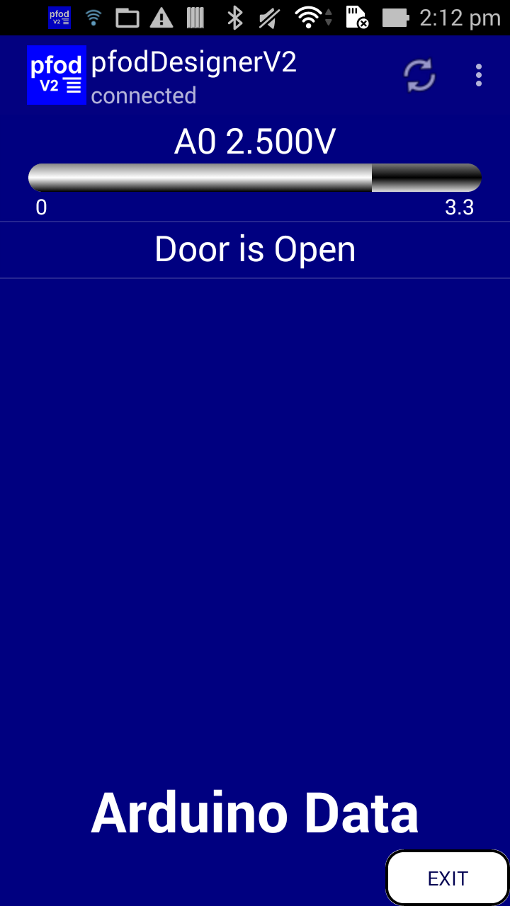
As
pfodApp re-requests this menu, it will update the display with the
latest data mapped to the range 0V to 3.3V.
The next menu item to be added is an On/Off Display which will show the current state of a 0 / 1 variable. It this tutorial we will monitor the state of the D4 digital input pin, High (1) or Low (0). On Adafruit Feather M0 RFM9x LoRa boards and Teensy/Feather Radio Wing stacks, D4 is used by the radio module and so is not available. Choose another input, say D6, instead.
Click Add Menu Item again and choose On/Off Display (Note carefully, this is NOT the On/Off Setting, but the On/Off Display further down the list of options.)

Scroll down and click on the “No connected to an I/O pin” button and select D4 as the pin to connect to this display. In our example the input to D4 is actually as door switch which is closed when the door is closed and open otherwise, so when the input is High the door is open and when the input is Low the door is closed.
Edit Leading Text to “Door is “. Note the space after 'is' and Edit Low text to “Closed” and Edit High text to “Open”. You can also change the text font size, colour etc as you wish.

Also
click on Display Text and Slider
until it says Display Text Only

That's
all that is need for displaying a digital input. Go back and preview
the menu.
The pfodDesignerV3 also makes it easy to control PWM outputs or let the user set a variable from a slider.
Click Add Menu Item again and choose PWM Output or Slider Input

By
default this menu item is initialized with the variable range set to
0 to 255 and the Display Max set to 100 and the Trailing Text set to
'%' so for Arduino compatible boards you can connect this menu item
to a PWM capable pin and control the PWM output from 0% to 100% by
sliding the slider. The slider is live so you can try it out.
Click on the “No connected to an I/O pin” button to connect this menu item to a PWM capable digital output, D5 for example. For Uno boards the PWM capable digital outputs are D3, D5, D6, D9, D10 and D11. For the Arduino 101 they are D3, D5, D6 and D9. Check the specifications of the particular board you are using to see which output can be used for PWM.
As with the other menu items, you can choose you own text, Display Max / Min, font formats etc. You can also just display the slider with no text if you wish.
Note: that the Data Variable Range sets the range values the slider sends back to the pfodDevice (your Arduino). The pfodApp always and only sends integral values, so while the display says 0 to 100% the slider actually sends back an integral value in the range 0 to 255 as set by the Edit Data Variable Range button. On the ESP8266 the default PWM range is 1023, so for those boards click the Edit Data Variable Range button and change the Edit Maximum Value to 1023. Notice that this does not change the Display Max which still shows 100%. It changes the mapping from the slider setting, so that 0 to 1023 will be displayed as 0 to 100%
Go back and preview the menu again.

This
menu preview is live and you can move the slider. If you add
sub-menus you can also open them and navigate in the same way pfodApp
will.
The next menu item to be added is On/Off Setting or Pulse which lets you control a digital output on or off or pulse it.
Click Add Menu Item again and choose On/Off Setting or Pulse
You
can click anywhere in the button to toggle the setting. Here we will
use this menu item to pulse the Arduino LED (D13) on for 10 sec.
after which it will turn off. The menu will update once a sec (the
Refresh Interval
you set
for this menu at the beginning of this tutorial) to show the current
state of the led. You can force it the led to turn off early by
clicking on the button again.
On Teensy/Feather Radio Wing stacks, D13 is used for SPI communication with the Radio Module and so cannot be used to drive the Teensy board LED. Select another pin instead, say pin 8.
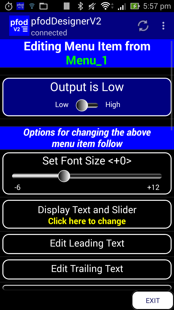
Set the Edit Leading Text to “LED is “ and Edit Low text to “Off” and Edit High text to “On”. Click on the “No connected to an I/O pin” button to connect this menu item to D13 (D8 on Teensy/LoRa). Click Display Text and Slider to Display Text Only and increase the font size to <+6> so the button is bigger and easier to click. You can also change the text font size, colour etc as you wish. Here I have set a Silver background and a Bold font

To
set the pulse length, click on the “Output
is not pulsed” button
and select Pulsed High
on the
top slider. The set a 10 sec pulse length.

Go
back and preview the menu again.

If
you don't like the way it looks you can go back the Editing
Menu_1 screen and edit the menu items.
I wanted a bit more space between the menu items and a larger font
for the Door is Open display.
Go back to Editing Menu_1 and click on Add Menu Item and scroll down and choose “Label”

Edit
Text to remove all the text so that you are left with a blank spacer.
You can adjust the size of the space with the Font Size setting. Here
I have set <-6> for a small spacer.![]()
Add another second Spacer and then go back to the Editing Menu_1 screen and scroll down to Move Items Up/Down

Click
on this and select a label to move and move to Door
is.
It will be inserted above the Door is display item. Move the other
label to PWM
to place
it between Door and PWM. Finally I also increased the font for the
Door is menu item to <+4> and made it bold, by choosing Edit
Menu and
then Door is
and
editing that button
The menu preview is now
![]()
Finally we will add a Chart to plot and log the value of A0.
Go back to Editing Menu_1 and click on Add Menu Item and scroll down and select Chart Button. pfodApp lets you have multiple charts and plots but, for simplicity, pfodDesignerV3 only allows one chart button per menu design and only up to 3 plots on that chart. Once you add a Chart Button, that option is removed. It will come back if you delete the Chart Button from your menu, or if you start a completely new menu using the Start new Menu button.
The pfodSpecification has a lot of charting and plotting options. Not all of them are available via pfodDesignerV3. Check the pfodSpecification.pdf for all the details.

You
can edit the Chart Button
like any other button. Here I will set the text of this button to
Voltage Plot
with a text size of <+4>

To
edit the Chart itself, click on the Chart
Button Voltage
Plot.
That will open the Editing Plots
for screen

As
you edit the chart and its plots, you can preview the result using
the Chart
Preview button.

Use
your mobile's back button to go back to the editing screen.
Set the Edit Chart Label to “Voltage at A0” or whatever label you want. Also set the Plot Data Interval. This interval at which your Arduino will send the plot data for logging and plotting. Plot data is automatically logged to a file on your Android mobile for download and further processing. Here I have left the plotting interval at 1 sec.
Click on Edit Plot 1 to open its editing screen.

Use
this edit screen to set the Edit
Plot Label to
“A0” and Edit
Plot yAxis Units to
“Volts”
As with the Display
Data screen above, set the Plot Data Variable Range and the Display
Max and Display Min so that the plot will display the real world
values. For Arduino 101 the data range is 0 to 1023 and the
represents 0V to 3.3V. For Adafruit M0 boards, the data range is
automatically set to 0 to 4096 for 0V to 3.3V, the default for these
boards.
So leave the Plot Data Variable range unchanged and Edit
Display Max to 3.3
Click on Not connected to an I/O pin to connect this Plot to pin A0 and click Plot is Auto Scale to toggle to Plot is Fixed Scale. Fixed scale sets the initial yAxis to the Display Max / Min, while Auto scale adjust the yAxis to just display the data. In any case is the plot data exceeds the Display Max / Min the plot will always auto scale to show all the data.
Use the Chart Preview button to check your settings. You can use two fingers to zoom the plots in or out.

Finally
click on Edit
Plot 2 and
Edit
Plot 3 to
and click the Hide
button to
hide them as we are only plotting on data variable in this example.
The Chart
Preview now
shows just one plot.

Going
back to the Editing Menu_1
screen and
selecting Preview
Menu show
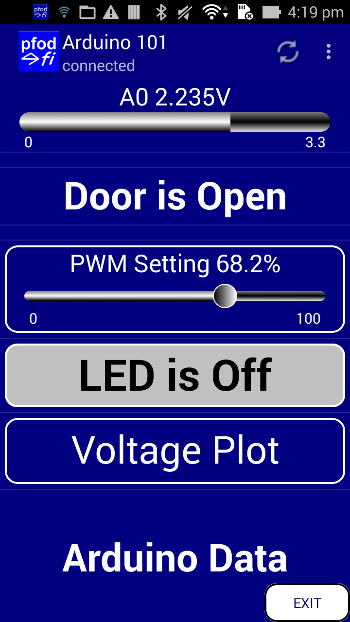
the final menu.

This
menu preview is 'live'. You can move the PWM slider and toggle the
LED on and off and click on the Voltage Plot button to open the plot
screen.
Back in the Editing Menu_1 screen you can delete un-wanted buttons as well as changing the menu name. The menu name is for your use only. It is shown in the list of Existing Menus, but is not displayed to the user when the menu is displayed on pfodApp.
Now that you have finished the design you can click Generate Code to open the Generate Code Menu.

From
this menu you can change which sort of hardware you are using to
communicate with.
If you set the Target at the start you don't
need to change it here. Changing the target here may remove all the
assigned pins if the boards differ.
The Arduino 101 uses BLE (Bluetooth Low Energy) for communication so click on Change Target and choose Bluetooth Low Energy (BLE) and then select Arduino/Genuino 101. If you are using different hardware choose the appropriate target. Most arduino communication shields connect via Serial at 9600, but check the specifications for your particular shield.
Use the back button to go back to the generate code screen.

Finally
click on the Write Code to file to generate Arduino sketch for this
menu for the Arduino 101. This button writes the sketch to a file on
your mobile and displays the last 4k bytes in a screen.
You can exit pfodDesignerV3 now, your design has been
saved and is available under “Edit existing Menu”.
You
MUST exit the pfodDesignerV3 to ensure the last block of code is
written to the file.
Connect your mobile to your computer and turn on the USB Storage, or use a Wifi File Transfer App to access your mobile's storage from your computer. (See pfodAppForAndroidGettingStarted.pdf for more details) Note: pfodDesignerV3 cannot access the SD card to save the generated code while it is being accessed by the computer as USB Storage, so turn of USB Storage before running the pfodDesignerV3 again.
Navigate to /pfodAppRawData and open the pfodDesignerV3.txt in a text editor (such as WordPad). The pfodDesignerV3.txt file is over written to each time you click “Generate Code”.
Open
the Arduino IDE and make a new sketch, delete any code from the
sketch window and then copy and past the generated code into the
Arduino IDE.
A copy of the
generated code is here.
To compile this code for Arduino 101 you need install the pfodParser library V2.35+ from http://www.forward.com.au/pfod/pfodParserLibraries/index.html. Some targets, such as Serial, don't need this library. The top of the generated file will indicate if it needs to be installed.

Compile and Upload the sketch to the Arduino 101 or whatever board you are using. If you are using a shield connected to Serial remember to remove the shield before programming as the shield is usually connected the the same pins (D0 and D1) as the USB.
Install pfodApp from GooglePlay and set up a connection for your board, as described in pfodAppForAndroidGettingStarted.pdf.
On connecting to the Arduino 101, pfodApp will display your designed menu. Now you click the LED button to turn the led on for 10sec and then turn off. The menu will update to LED is Off when the led turns off. If you connect the D4 input to GND then the menu will show Door is Closed.
You can use the PWM slider to control the input voltage to A0. Connect a 47K resistor from D5 to A0 and connect a 470nF capacitor from A0 to GND (Note: If the capacitor you are using has a +/- make sure the – is connect to GND). This RC network smooths out the PWM pulses to give an approximately steady DC voltage. Then as you adjust the PWM slider the voltage measured at A0 changes and the menu shows the changed value.
The
plot will also show the varying voltage measured at A0.
You
can use two fingers to zoom in to get a closer look at the ripple at
each level.
If you
look at the pfodApp's Debug View accessed from your mobile's menu you
will see the menu update messages are very short because pfodApp
caches the menu and there after the Arduino sketch only send the
update values for each menu item instead of resending the whole menu
text each second. If you look at the pfodApp's Raw Data view, you
will see the CSV data records that are being sent and logged. This is
where the plot gets its data from. The two ,, on the end of each
record are place holders for plot 2 and plot 3's data which were not
used in this example.
pfodApp automatically saves the plot data on your Android mobile under the directory /pfodAppRawData, in a file with the same name as the connection, with any spaces replaced with _. For example if the connection you created in pfodApp to connect to the Arduino 101 was named by you as “Arduino 101” then the plot data is saved in the file /pfodAppRawData/Arduino_101.txt
The name of the raw data file is also displayed by pfodApp as you exit the app.

You
can transfer this plot data file to your computer for further
processing.
This completes the tutorial. Bluetooth Low Energy (BLE) made simple with pfodApp has examples of using various other BLE shields. Simple Home Automation for Beginners looks at attaching relays, so that you can switch real things on and off.
But pfodApp can do much more than this. The pfod protocol is a rich but simple one and contains much more then just simple menus. Check out the full pfodSpecification.pdf for all the details and examples. Also see www.pfod.com.au for numerous example projects. All the screens used by the pfodDesignerV3 are standard pfod screens. The pfodDesignerV3 is just a pfodApp connected to a back-end that keeps track of your selections and serves up the requested screens. From the pfodDesignerV3 you can use the mobile's menu button to open the Debug View to see what pfod messages are being sent to generate the pfodDesignerV3 screens and what commands are sent back by your actions.
AndroidTM is a trademark of Google Inc. For use of the Arduino name see http://arduino.cc/en/Main/FAQ
The General Purpose Android/Arduino Control App.
pfodDevice™ and pfodApp™ are trade marks of Forward Computing and Control Pty. Ltd.

Contact Forward Computing and Control by
©Copyright 1996-2020 Forward Computing and Control Pty. Ltd.
ACN 003 669 994