
|
Home
| pfodApps/pfodDevices
| WebStringTemplates
| Java/J2EE
| Unix
| Torches
| Superannuation
| CRPS Treatment
|
| About
Us
|

|
Bluetooth Low Energy (BLE) made simple with pfodApp™
|
by Matthew Ford 30th September 2024
(originally posted 26th May 2015)
© Forward
Computing and Control Pty. Ltd. NSW Australia
All rights reserved.
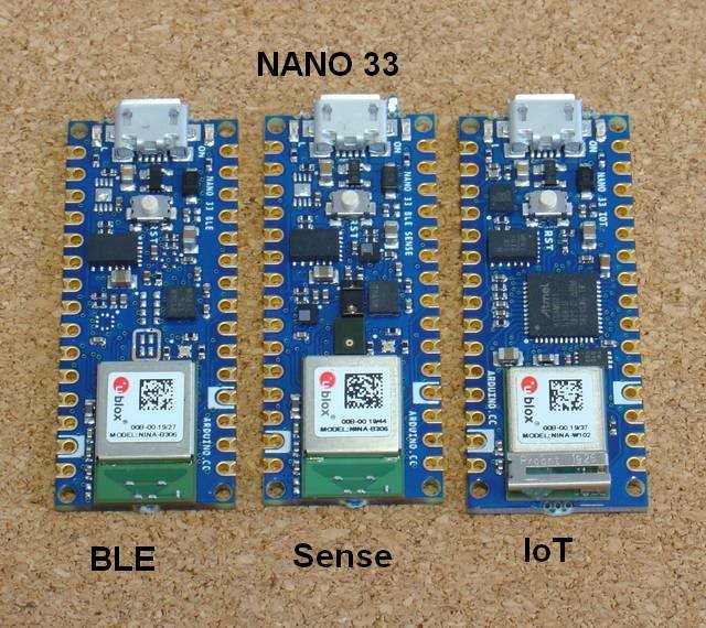
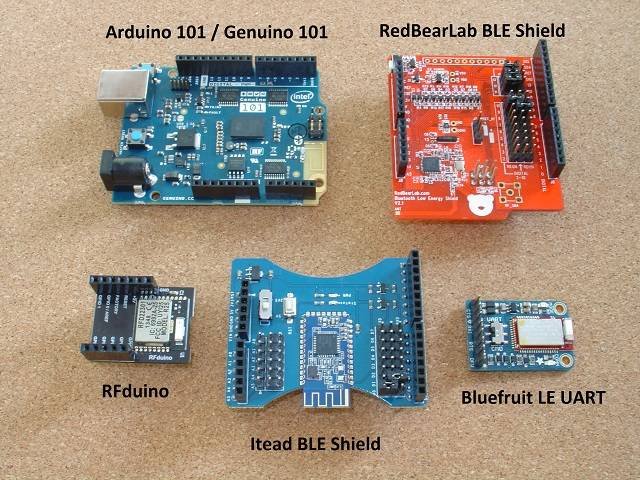

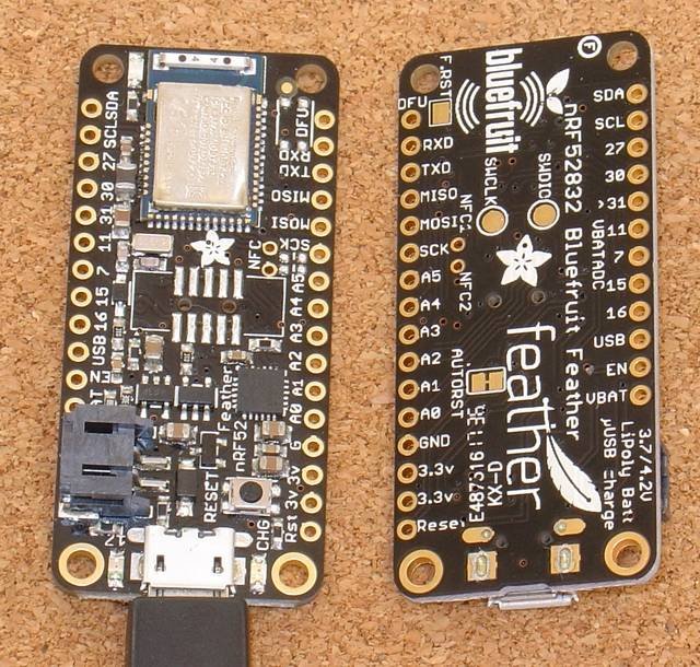


Update 30th
September 2024 – Added High
Speed NANO 33 BLE remote data logging and plotting
Update 4th
July
2020 – Added NANO 33
Update 21th
June
2020 – Added Arduino BBC microbit code
Update 20th
June
2020 – Fixed pfodDesigner support for Arduino nRF52 Feather
board library V0.20.1
Update 9th
January
2020 – Add note for installing RFduino support now that the
company website is gone
Update 14th
December
2018 – Added Very Low Power BLE support for nRF52 chips, e.g.
RedBear NanoV2
Update 29th
October
2018 Revise pfodBLEBufferedSerial comments
Update 30th
May
2018 Added ESP32 boards
Update 16th
November
2017 Added Adafruit Bluefruit Feather nRF52 board.
Update 15th
November
2017 Some BLE boards / software stacks deliver the same cmd twice in
quick succession. Update to pfodApp
V3.322+ and pfodParser
V3.17+ to solve this. pfodApp V3.322+ adds a cmd sequence number and
pfodParser V3.17+ filters out duplicate cmds.
Update 1st
November
2017 Added pfodBLEBufferedSerial example for Adafruit BLE UART
Update
15th
September
2017 Added RedBear BLE Nano V2
Update 30th
August
2017 Added RedBear BLE Nano
Update 18th
July
2017 Intel has announced End-Of-Life
for
Arduino101
Update 15th
May
2017: Arduino101 V2.0.2 of Curie Firmware drops connections. Use
V1.0.7 instead. See Arduino
101 / Genuino 101 below
for how to downgrade the firmware
Update 15th
January
2017: Lancaster Uni is changing the micro:bit UART service (issue
#259). pfodApp supports both the old and new style services so
this change will not effect pfodApp users.
Update 25th
August
2016: added BBC micro:bit support.
Update 16th
August
2016: added Adafruit Feather LE SPI board support.
Update 1st
July
2016: pfodApp V2.0.213+ needs pfodParser library V2.35+. Small change
to image dwg BLE examples.
Update 2nd
June
2016: Revised All code for latest board libraries and for pfodApp V2,
using pfodDesignerV2. The result is improved connection reliability
and speed.
This tutorial covers ten (13) common BLE modules and for each one shows you how to control them via custom menus from your Android mobile without doing any programming.
First install the pfodParser.zip and pfodDwgControls.zip libraries from here.
The
free pfodDesignerV2
Android app lets you create custom menus and then generates all the
code for your particular BLE module. pfodApp
is then used to display your custom menu on your Android mobile and
let you control your module.
No
Android or Arduino coding is required.
See this page for BLE problems and solutions
The modules covered are:-
Very
Low Power BLE nRF52, e.g. Nano V2, less than 100uA when connected
or advertising
High
Speed Remote BLE Data Logging and Plotting using
Arduino NANO 33 BLE. No Android programming required – Plot and
log data on your mobile from your Arduino NANO 33 BLE at ~100Hz.
NANO
33 BLE (and WiFi)
ESP32
Adafruit
Bluefruit Feather nRF52 – Adafruit Feather nRF52832,
Adafruit Feather nRF52840 Express, Nordic nRF52840DK (PCA10056),
Adafruit Feather Bluefruit Sense, Adafruit ItsyBitsy nRF52840
Express, Adafruit Circuit Playground Bluefruit, Adafruit CLUE,
Adafruit Bluefruit Metro nRF52840 Express, Particle Xenon, Raytac
MDBT50Q-RX Dongle
Arduino 101 / Genuino
101
RFduino
RedBearLab
BLE Nano V2 and V1-V1.5 ~7mA
RedBearLab
BLE Shield
Adafruit Bluefruit LE UART
Friend and Flora Boards
Adafruit
Bluefruit LE SPI (i.e. Bluefruit LE Shield, Bluefruit LE Micro,
Feather 32u4 Bluefruit LE, Feather M0 Bluefruit LE or Bluefruit LE
SPI Friend)
Itead BLE shield and other HM-10
modules
BBC micro:bit – programmed
via Arduino
Support for more modules will be added as requested.
For each of these modules the hardware and software set up is covered and code for your custom menu is generated. Also a more extensive sample sketch is supplied for each module. That sample sketch covers more features of pfodApp such as:- sub-menus, plotting and data logging, text input, sliders and multi- and single- selection lists. BLE is designed for short packets so design your menus accordingly and optimize the responses to only send the changes not the whole menu. For simplicity the Sample Screens sketches dos not do this optimization.
Finally there are a few BLE trouble shooting tips.
Bluetooth Low Energy (BLE) or Blutooth V4 is a completely different version of Bluetooth. BLE has been optimized for very low power consumption. pfodApp is a general purpose Android app whose screens, menus, buttons, sliders and plots are completely defined by the device you connect to.
BLE only sends 20 bytes in each message. Fortunately the pfod Specification was designed around very small messages. Almost all of pfod's command are less then 20 bytes. The usual exception is the initial main menu message which specifies what text, menus, buttons, etc pfodApp should display to the user, but the size of this message is completely controlled by you and you can use sub-menus to reduce the size of the main menu.
The pfod specification also has a number of features to reduce the message size. While the BLE device must respond to every command the pfodApp sends, the response can be as simple as {} (an empty response). If you need to update the menu the user is viewing in response to a command or due to a re-request, you need only send back the changes in the existing menu, rather then resending the entire menu. These features keep the almost all messages to less than 20 bytes.
pfodApp V2 menus have been re-designed to further reduce the message sizes. pfodApp V2 caches menus across re-connections so that the whole menu only needs to be sent once. Thereafter short menu updates can be sent.
Update 30th September 2024 – pfodApp V3.0.424+ now attempts to negotiate BLE mtu's of upto 517 bytes, which allows for much higher through put. See High Speed Remote BLE Data Logging and Plotting. pfodDesigner V3.0.4241+ generated sketches for Arduino NANO 33 BLE which use this improved through put.
Before looking at each of these BLE modules, pfodDesignerV2 will first be used to create a custom menu to turn a Led on and off. pfodDesignerV2 can then generate code tailored to the particular hardware you select.
You can skip over this step and come back to it later if you like. The section on each module, below, includes the completed code sketch for this example menu generated for that module.
The free pfodDesignerV2 is used to create the menu and show you an accurate preview of how the menu will look on your mobile. The pfodDesignerV2 allows you to create menus and sub-menus with buttons and sliders optionally connected to I/O pins and generate the sketch code for you (see the pfodDesigner example tutorials) but the pfodDesignerV2 does not cover all the features pfodApp supports. See the pfodSpecification.pdf for a complete list including data logging and plotting, multi- and single- selections screens, sliders, text input, etc. Each BLE device below has a sample screens sketch illustrating some of these other features.
The tutorial Design a Custom menu to turn the Arduino Led on and off has step by step instructions for creating this menu using pfodDesignerV2.
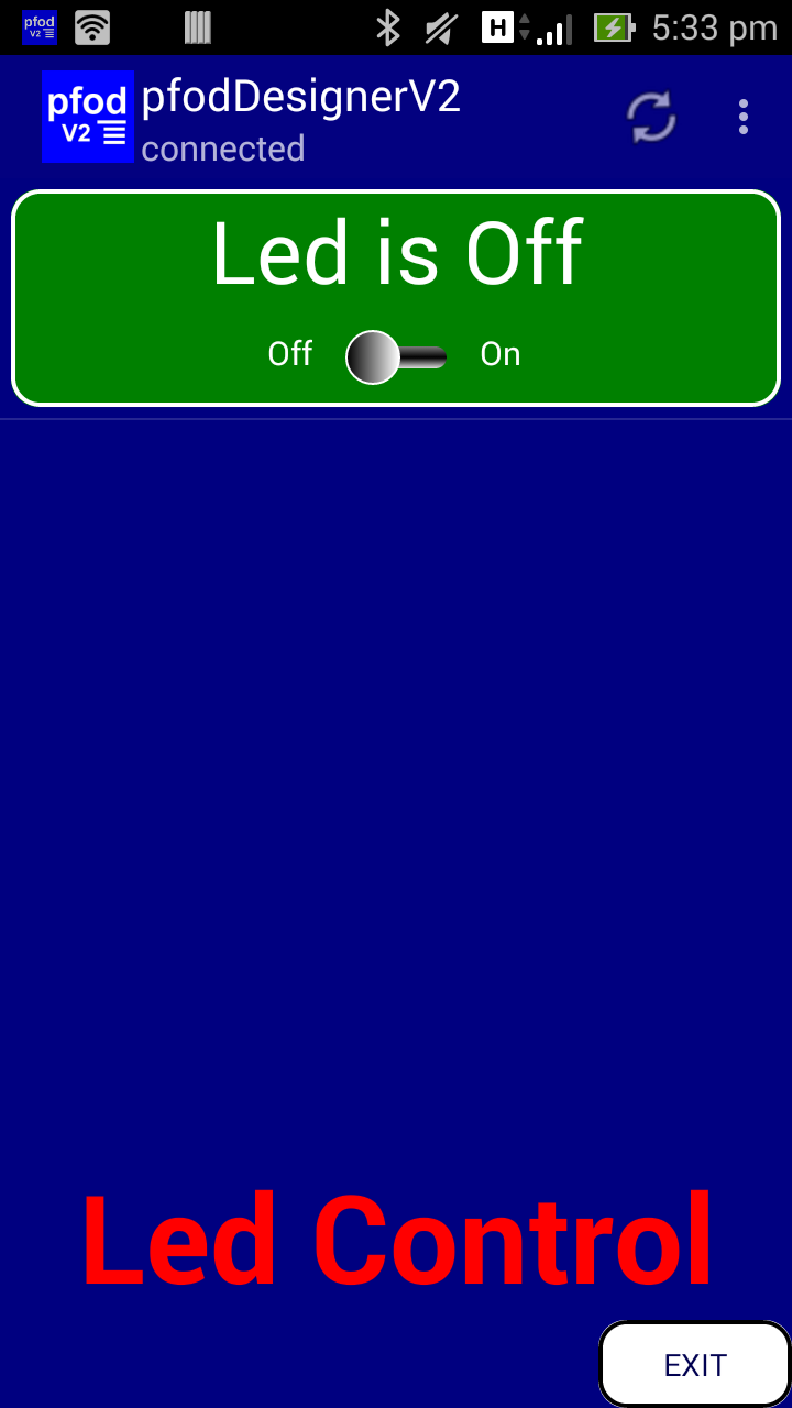
If
you don't like the colours of font sizes or the text, you can easily
edit them in pfodDesignerV2 to whatever you want and see a WYSIWYG
(What You See Is What You Get) display of the designed menu.
The rest of this tutorial will use that menu design to control the LED via various BLE modules. pfodDesignerV2 lets you generate the Arduino code for this menu for each of these BLE modules as well as WiFi, Ethernet, ESP8266, SMS and Bluetooth shields.

The
Itead
BLE shield is the simplest BLE shield to use. It provides AT
commands to configure it and then just runs as a Serial to BLE
bridge.
In
this tutorial we are using an Arduino UNO as the base board. Only two
things need to be done to the Itead BLE shield to configure its
hardware for use. No AT commands are need.
i) set the TX RX links
as shown above, D0 linked to the TX side and D1 linked to the RX
side
ii) set the 5V / 3V switch to 5V, since the UNO is a 5V board


That's
all! Now remove the BLE shield from the UNO to program.
In the pfodDesignerV2 choose the Generate Code button for the menu you have designed (see Design a Custom menu to turn the Arduino Led on and off has step by step instructions). To generate the code, choose from the Bluetooth Low Energy sub-menu, the Itead BLE Shield.

For
the Itead BLE shield, a Serial connection at 9600 baud is set since
the Itead
BLE shield,
as set up above, just connects to the Tx/Rx of Uno's Serial
connection. Click on “Write Code to file” to generate the
code and write it to the pfodDesignerV2.txt file.

Then transfer the /pfodAppRawData/pfodDesignerV2.txt file from your mobile to your computer as described in Design a Custom menu to turn the Arduino Led on and off. Copy and paste the code into the Arduino IDE and program the UNO board. Here is the completed sketch, Itead_BLE_led_control.ino
Remember to remove the Itead BLE shield before programming the UNO, as the Itead BLE shield is connected the the same pins (D0 and D1) as the USB.
Plug the Itead BLE shield back in and open pfodApp and create a BLE connection for it as described in pfodAppForAndroidGettingStarted.pdf. Then connect, and pfodApp will display the menu you have designed and allow you to control the LED on the Arduino Uno board.
The pfodDesignerV2 only supports a sub-set of the screens that pfodApp supports. For a complete list see the pfodSpecification.pdf. The sketch SimpleBLEScreensSerial.ino provides examples of various screens, plotting and data logging. Most of the screens have no formatting to keep the messages clear and simple. The color selector under Sliders is an exception. You can add your own colours and font styles, using the pfodDesignerV2 as a guide. Also see the pfodDemo app for other examples.
The SimpleBLEScreensSerial.ino sketch needs the pfodParser.zip and pfodDwgControls.zip libraries to be installed first.


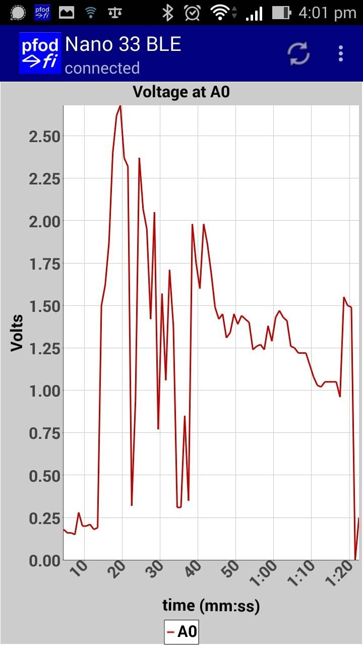
This page, Arduino NANO 33 Made Easy covers how to connect to Arduino NANO 33 BLE / Sense and IoT via BLE (and WiFi for the IoT) using pfodDesignerV3 to generate the code and pfodApp to connect. That page also includes simple sketches that connect via the free Nordic nRF UART 2.0 BLE app to send user defined command words and via a Telnet program to connect via WiFi for the IoT board

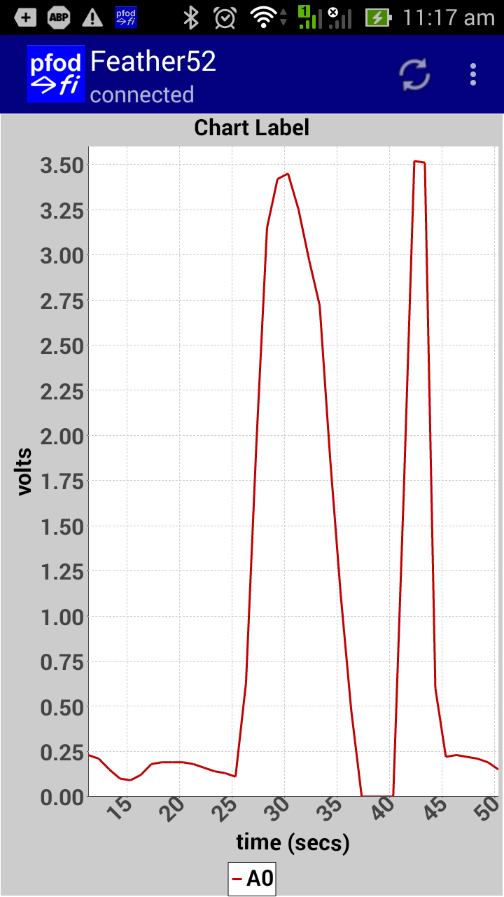

The Adafruit Bluefruit Feather nRF52 is a stand
alone board with a LiPo charger and battery plug. It runs at 64Mhz
and supports Bluetooth Low Energy V5
See the Adafruit
Feather nRF52 LE - Custom Controls with pfodApp tutorial for
details on using Feather nRF52 with pfodApp and
pfodDesignerV3.0.3760
Includes support for Adafruit Feather
nRF52832, Adafruit Feather nRF52840 Express, Nordic nRF52840DK
(PCA10056), Adafruit Feather Bluefruit Sense, Adafruit ItsyBitsy
nRF52840 Express, Adafruit Circuit Playground Bluefruit, Adafruit
CLUE, Adafruit Bluefruit Metro nRF52840 Express, Particle Xenon,
Raytac MDBT50Q-RX Dongle

The
Adafruit
Bluefruit LE UART Friend and Flora
Bluefruit LE boards are the next simplest BLE to use, although
you would not guess that from reading Adafruit's
introduction to this board. It also provides AT commands to
configure it, but as it comes is will run as a Serial to BLE bridge
at 9600 baud (fixed). However unlike Itead's BLE offering, you need
to do some soldering to get Adafruit's board connected.
The Adafruit BLE UART has hardware flow control, but Arduino UNO and Mega2560 and most other boards don't support that. However see below for solution to the problem of sending large BLE messages without using the hardware flow control.
Solder in the header provided with the board and set
the UART / CMD switch to UART. 
Then
connect the board to an Arduino UNO using the following connections
:-
TXO to Arduino RX (Pin 0) (Green lead in photo)
RXI to
Arduino TX (Pin 1) (Brown lead in photo)
VIN to 5V (Red lead in
photo)
CTS to GND (Yellow lead in photo)
GND to GND (Black lead
in photo)
That's it set up done.
In the pfodDesignerV2 choose the Generate Code button for the menu you have designed (see Design a Custom menu to turn the Arduino Led on and off has step by step instructions). To generate the code, choose from the Bluetooth Low Energy sub-menu, the Adafruit's Bluefruit LE UART. Go back and click on “Write Code to file” to generate the code and write it to the pfodDesignerV2.txt file.
Then transfer the /pfodAppRawData/pfodDesignerV2.txt file from your mobile to your computer as described in Design a Custom menu to turn the Arduino Led on and off. Copy and paste the code into the Arduino IDE and program the UNO board. Here is the completed sketch, Adafruit_BLE_UART_led_control.ino
Remember to remove the TX and RX leads to the Bluefruit LE UART before programming the UNO, as the Bluefruit LE UART is connected the the same pins (D0 and D1) as the USB.
Plug the TX and RX leads back in and open pfodApp and create a BLE connection for it as described in pfodAppForAndroidGettingStarted.pdf. Then connect and pfodApp will display the menu you have designed and allow you to control the LED on the Arduino Uno board.
The pfodDesignerV2 only supports a sub-set of the screens that pfodApp supports. For a complete list see the pfodSpecification.pdf. The sketch SimpleBLEScreensSerial.ino provides examples of various screens, plotting and data logging. Most of the screens have no formatting to keep the messages clear and simple. The color selector under Sliders is an exception. You can add your own colours and font styles, using the pfodDesignerV2 as a guide. Also see the pfodDemo app for other examples. See above for some screen shots from the SimpleBLEScreensSerial.ino The SimpleBLEScreensSerial.ino sketch need the pfodParser.zip and pfodDwgControls.zip libraries to be installed first.
Adafruit BLE UART has hardware flow control. However the Arduino Uno and Mega and most other Arduino boards do not support hardware flow control on the Serial TX/RX. So to make the BLE UART work the CTS lead is earthed as shown above and the RTS (which stops the Arduino from sending) is ignored.
This is fine for sending a few 10's of bytes, but when sending dwgs, which typically contain 100's of bytes for the initial load, the Adafruit BLE UART looses parts of the message and the pfodApp does not get a complete response. In the problem reported above no version string was specified in the arduino code so the complete dwg was being reloaded each time which made the problem more likely to occur.
The correct way to fix this would be to use the hardware flow control line provided by the Adafruit BLE UART, however Arduino Uno and Mega and most other boards do not support hardware flow control. The solution in this case is to buffer the serial output and send 20 bytes (a BLE message size) at a time with a delay between blocks to allow the Adafruit BLE UART to transmit them to pfodApp.
pfodParser V3.32+ includes a pfodBLEBufferedSerial class which does this buffering. pfodParser library V3.32+ includes a complete example sketch, pfodBLEBufferedSerialExample.ino
To use the buffer add its include
#include
<pfodParser.h>
#include <pfodDwgControls.h>
#include
<pfodBLEBufferedSerial.h>
create an instance
pfodParser
parser(""); // create a parser to handle the pfod
messages
pfodDwgs dwgs(&parser); // drawing
support
pfodBLEBufferedSerial bufferedSerial; // default 1024
buffer
and modify the parser.connect statement
to
parser.connect(bufferedSerial.connect(&Serial));
// connect the parser to the i/o stream via buffer
This sets up a 1024 byte buffer which is the maximum
bytes for a single response. If your responses are shorter you can
create a smaller buffer. Particularly for Uno which has limited stack
available. It this particular case the whole dwg was 370 bytes and
that was the longest msg response being sent so a 400 byte buffer is
appropriate.
pfodBLEBufferedSerial
bufferedSerial(400); // create a 400 byte buffer instance
pfodBLEBufferedSerial use malloc to allocate buffer, if malloc fails then a default static 32byte buffer is used. malloc uses dynamic memory not already used by variables, i.e. bytes free for local variables, but you need to leave some bytes for local variables, say 300 or so, after malloc. For example if compiler shows "leaving 1135 bytes for local variables" then use pfodBLEBufferedSerial(800) or less. pfod messages are ALWAYS less then 1024 bytes so the buffer size NEVER needs to be larger then 1024. The sample pfod messages at the top of the pfodDesigner generated code will give you an idea of the length of the messages being sent.

The
Adafruit Bluefruit LE SPI boards include:- Bluefruit
LE Shield, Bluefruit
LE Micro, Feather
32u4 Bluefruit LE, Feather
M0 Bluefruit LE or Bluefruit
LE SPI Friend The board shown here is the Feather 32u4 Bluefruit
LE.
No hardware set up is needed but you need to install an extra board configuration and an extra support library (in addition to the pfodParser Library)
Open
Arduino V1.6.8's File->Preferences and add this url to the
“Additional Boards Manager URLs'” (comma
separated)
https://adafruit.github.io/arduino-board-index/package_adafruit_index.json
You
also need to download the Adafruit_BluefruitLE_nRF51-master.zip from
https://github.com/adafruit/Adafruit_BluefruitLE_nRF51
(click the Clone or Download button and choose Download
Zip)
If
you are on Windows, you may also need to download and install some
drivers from
https://github.com/adafruit/Adafruit_Windows_Drivers/releases/download/1.0.0.0/adafruit_drivers.exe
Adafruit
has detailed instructions on setting up your Arduino IDE to program
these boards.
A cached copy V1.9.4 of
Adafruit_BluefruitLE_nRF51-master.zip
is here in case a later version breaks something.
The pfodDesignerV2 only supports a sub-set of the screens that pfodApp supports. For a complete list see the pfodSpecification.pdf. The sketch Bluefruit_SPI.ino provides a simple example of turning the LED on and off, setting PWM output and charting the ADC A0 voltage reading. This Android interface was completely designed by pfodDesignerV2, which then generated the complete Arduino sketch, Bluefruit_SPI.ino You can use pfodDesignerV2 to create your own interface for these boards.


The
RFduino
is my next favourite board. It is small and simple and has commands
to go into low power mode and has neat battery shield you can just
plug-in, shown above with the optional Led, push button shield on
top. There is also a relay shields, a servo shield, etc, available.
To program it you need to add the USB shield shown above (under the main board). While the USB shield is designed to plug directly into your USB port, I found that very inconvenient on my laptop so I add a USB extension cable.
No hardware set up is needed but you need to install an extra board configuration.
Open
Arduino V1.6.8's File->Preferences and add this url to the
“Additional Boards Manager URLs'” (comma
separated)
Originally the URL was
http://rfduino.com/package_rfduino_index.json,
sadly
the supporting website for installing the Arduino IDE board support
is gone.
However you can use this URL in the Preferences
https://gist.github.com/per1234/f7822073e05276c4243740eaab4235d1/raw/9c34051294ddd54dbbdf3bec392df0afef8da938/package_rfduino166_index.json
which provides access to V2.3.3 (and V2.3.2) and installs the
files from https://github.com/RFduino/RFduino/archive/v2.3.3.tar.gz
Then open the Tools->Board->Board Manager and type RFduino into the search bar. Then install the RFduino board support. (V2.3.1 was used for these examples)
You
will get an error message Invalid
library found in
...\AppData\Local\Arduino15\packages\RFduino\hardware\RFduino\2.3.1\libraries\RFduinoNonBLE:
because that 'library' has no library code, just examples. Just
ignore this error.
When you compile you will also get a warning
Warning:
platform.txt from core 'RFduino Boards' contains deprecated recipe
but
the compile and load seems to work just fine.
If you have problems when compiling, like RFduino not found, then close the Arduino IDE, rename you existing Arduino15 directory to Arduino15_old, reopen the Arduino IDE (it will create a new empty Arduino15 directory) and then add the URL to the preferences and re-install the RFduino support.
The RFduino board does not have an LED on D13, but instead as tri-colour leds on its Led push button shield driven by D2,D3 and D4. So go back into the pfodDesignerV2 and edit your Led Control menu you have designed (see Design a Custom menu to turn the Arduino Led on and off has step by step instructions) to change the output connected to the LED On/Off slider from D13 to D3 (say) for the Green led

Then
in the Generate Code menu, choose from the Bluetooth Low Energy
sub-menu, the RFduino
setting.
Go back and click on “Write Code to file” to generate the
code and write it to the pfodDesignerV2.txt file.
Then transfer the /pfodAppRawData/pfodDesignerV2.txt file from your mobile to your computer as described in Design a Custom menu to turn the Arduino Led on and off. Copy and paste the code into the Arduino IDE and program the RFduino board. Here is the completed sketch, RFduino_led_control.ino
Open pfodApp and create a BLE connection for it as described in pfodAppForAndroidGettingStarted.pdf. Then connect and pfodApp will display the menu you have designed and allow you to control the Green LED on the RFduino Led shield. You can use the pfodDesignerV2 to add two other controls for the Red and Blue leds also.
The pfodDesignerV2 only supports a sub-set of the screens that pfodApp supports. For a complete list see the pfodSpecification.pdf. The sketch SampleScreensRFduino.ino provides examples of various screens, plotting and data logging. Most of the screens have no formatting to keep the messages clear and simple. The color selector under Sliders is an exception. You can add your own colours and font styles, using the pfodDesignerV2 as a guide. Also see the pfodDemo app for other examples.
The SampleScreensRFduino.ino has been customized to the RFduino. Instead of plotting A0 against time, it plots the internal temperature in deg C. Also the Colour Selector Example actually changes the colour of the RGB led on the optional Led push button shield. You need to reflect the led output off a white card to mix the colour output of the three leds.
The SampleScreensRFduino.ino sketch needs the pfodParser.zip and pfodDwgControls.zip libraries to be installed first.

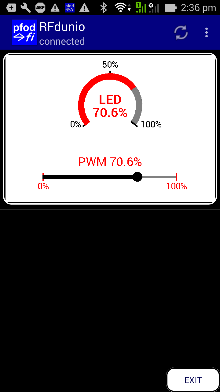

Arduino
released Arduino
101 / (Genuino
101 outside USA) which has an Intel Curie processor,
accelerometer and clock as well as BLE connectivity in an UNO form
factor.
Intel has announced End-Of-Life for Arduino101 so it is not recommended for new projects.
The built in accelerometer and clock are a plus, but the size is not as convenient for a wearable application, however the standard UNO form factor means you can easily add a wide variety of other shields. This board can be coded to appear as any of the 'standard' BLE services. The pfodDesignerV2 generated code configures the Arduino 101 / Genuino 101 as a Nordic BLE UART service.
You need to install Arduino V1.8.2 IDE and then from the Board Manager add the Curie board support (select V1.0.7 not V2.0.2). This adds and installs USB virtual COM drivers as well. There is also some hardware set up to be done on the board itself. Arduino V1.8.2 and Curie V1.0.7 work, but not Curie V2.0.2. Curie V2.0.2 looses connections.
To downgrade from Curie V2.0.2 to V1.0.7
i)
goto board manager and remove Curie V2.0.2
ii) stop
IDE V1.8.2
iii) unplugged the Arduino101 board
iv) start IDE
V1.8.2 and installed Curie V1.0.7 from board manager
v) plugged
the Arduino101 board in and waited for the USB drivers to install
vi)
select Board Arduino101, then select Programmer →
“Arduino/Genuno 101 Firmware Updater” and then reburn the
boot loader on the Arduino101 with the “Burn Bootloader”
option.
vii) unplug the board.
viii) plugged the board back
in
ix) reloaded the sketch
Fixing the EEPROM errors:
Curie
V1.0.7 was sloppy in its definition of the EEPROM support and
included source code in the header file. This results in multiple
function definition errors when compiling. To fix this go to the
Curie package
directory
C:\Users\...\AppData\Local\Arduino15\packages\Intel\hardware\arc32\1.0.7\libraries\EEPROM\src
where
… is your Windows username
and replace existing EEPROM.h
with these two files (from V2.0.2) EEPROM.h
and EEPROM.cpp
In the pfodDesignerV2 choose the Generate Code button for the menu you have designed (see Design a Custom menu to turn the Arduino Led on and off has step by step instructions). To generate the code, choose from the Bluetooth Low Energy sub-menu, Arduino/Genuino 101. Go back and click on “Write Code to file” to generate the code and write it to the pfodDesignerV2.txt file.
Then transfer the /pfodAppRawData/pfodDesignerV2.txt file from your mobile to your computer as described in Design a Custom menu to turn the Arduino Led on and off. Copy and paste the code into the Arduino IDE and program the 101 board. Here is the completed sketch, Arduino101_led_control.ino Note: It takes a few seconds for the 101's serial port to come up after programming. Just keep clicking on Tools in the IDE until the port shows up.
Open pfodApp and create a BLE connection for it as described in pfodAppForAndroidGettingStarted.pdf. Then connect and pfodApp will display the menu you have designed and allow you to turn the Arduino/Genuino 101's led on and off.
The pfodDesignerV2 only supports a sub-set of the screens that pfodApp supports. For a complete list see the pfodSpecification.pdf. The sketch SampleScreensArduino101.ino provides examples of various screens, plotting and data logging. Most of the screens have no formatting to keep the messages clear and simple. The color selector under Sliders is an exception. You can add your own colours and font styles, using the pfodDesignerV2 as a guide. Also see the pfodDemo app for other examples.
The
SampleScreensArduino101.ino
has been customized to the Arduino 101 / Genuino 101. Instead of
plotting A0 against time, it plots the 3 axis accelerometer outputs
scaled so that 1024 is about 1G.
The SampleScreensArduino101.ino
sketch needs the
pfodParser.zip and pfodDwgControls.zip libraries to be installed
first.


The
RedBearLab's
Bluetooth Low Energy Shield V2.1 is one
of a number of RedBearLab modules that uses a Nordic nRF8001 chip.
The picture above shows this shield plugged in on top of an Arduino
UNO, but the larger
memory of a Arduino Mega 256 is needed for the latest library and
pfodDesignerV2 generated code.
RedBearLab provides a library to program the shield, but here I have
used the BLEPeripheral
library V0.4.0 instead because it is almost exactly the same as
code used for the Arduino 101/Genuino 101 board.
You
need to install the BLEPeripheral
library. Open the Library Manager in the IDE and type
BLEPeripheral in the search bar. Select BLEPeripheral
by Sandeep Mistry V0.4.0 and
install it.
You can try later versions of the BLEPeripherial
library, but V0.4.0 is that one that has been tested here. A copy of
that V0.4.0
arduino-BLEPeripheral-master.zip file is here in case later
versions break something.
Configure the boards jumpers as shown below. Pins 13,12,11 SPI to ICSP side. Pin 9 to REQN side and Pin 8 to RDYN side.

That's
it, configuration complete. Plug the shield into the Arduino UNO
board.
In the pfodDesignerV2 choose the Generate Code button
for the menu you have designed (see Design
a Custom menu to turn the Arduino Led on and off has step by step
instructions). To generate the code, choose from the Bluetooth Low
Energy sub-menu, the RedBearLab
BLE Shield.
Go back and click on “Write Code to file” to generate the
code and write it to the pfodDesignerV2.txt file.
Then transfer the /pfodAppRawData/pfodDesignerV2.txt file from your mobile to your computer as described in Design a Custom menu to turn the Arduino Led on and off. Copy and paste the code into the Arduino IDE and program the Mega 256 board. Here is the completed sketch, RedBearLab_led_control.ino
Open pfodApp and create a BLE connection for it as described in pfodAppForAndroidGettingStarted.pdf. Then connect and pfodApp will display the menu you have designed and allow you to control the LED on the Arduino Mega 256 board.
The pfodDesignerV2 only supports a sub-set of the screens that pfodApp supports. For a complete list see the pfodSpecification.pdf. The sketch SampleScreensRedBearLab.ino provides examples of various screens, plotting and data logging. Most of the screens have no formatting to keep the messages clear and simple. The color selector under Sliders is an exception. You can add your own colours and font styles, using the pfodDesignerV2 as a guide. Also see the pfodDemo app for other examples.
The SampleScreensRedBearLab.ino sketch need the pfodParser.zip and pfodDwgControls.zip libraries to be installed first.

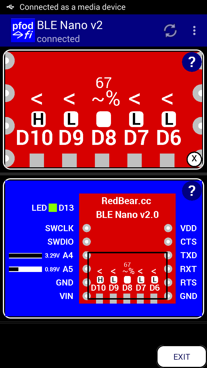
The RedBearLab BLE Nano V2 is a small stand
alone board that needs a programming board to download the sketches.
Nano
V2 is now available from Particle
These
sketches use ~7mA. For very low power BLE for Nano V2, i.e. <100uA,
see
Easy
Very Low Power BLE in Arduino
See Redbear
BLE Nano V2 Custom Controls with pfodApp tutorial for details on
using BLE Nano V2 with pfodApp and pfodDesignerV2.
pfodDesignerV3
rev3441+ generates very
low power sketches for Nano V2
For
RedBear
Nano V1-V1.5 see this tutorial.


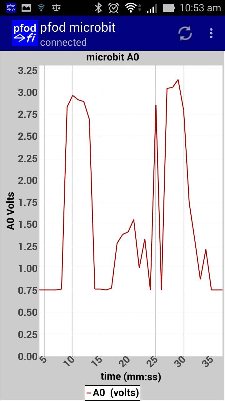
The BBC micro:bit can be programmed via the the Arduino IDE using the board support "Nordic Semiconductor nRF5 Boards" by Sandeep Mistry. The setup to program microbit via the Arduino IDE has a few steps. Adafruit has a detailed description of the steps involved (local copy here). Also install the following supporting libraries, Adafruit Microbit Library V1.2.2, Adafruit_GFX_Library 1.9.0 and Adafruit BUS IO library V1.3.2 via the Arduino Library Manager.
The pfod_microbit.ino sketch was generated by pfodDesignerV3.0.3760+ and produces the above Android control menu and plot.
You can also program the micro:bit is programmed via Netbean (C++), and other on-line languages. The tutorial Android Controlled C++ micro:bit shows you how to set up the Netbeans IDE and support libraries to compile the code generated by pfodDesignerV3 and program your micro:bit to display the above menu and chart.
If you have trouble downloading your sketch to the microbit, it may be stuck in maintenance mode. You can usually re-enter normal operating mode by unpluginng the board from USB, making sure the Reset button is not pressed, and plug the board back in. If that does not work then unplug the USB and connect a 3V battery to power up the microbit before plugging the USB cable in.


ESP32 is a low cost dual processor chip, with support for WiFi, Bluetooth Classic and BLE (Bluetooth Low Energy). Although the chip has been out for a number of years, code support for Arduino is still not complete (as at April 2018), but this tutorial and code generator fills in the missing BLE and analogWrite functions.
That web page covers setting up the Arduino IDE to program the ESP32 for BLE, Bluetooth or WiFi connections. The pfodDesigner generates code for each of these connection types and also generates code to simulate the missing analogWrite function.
The Arduino add-on supports some 31 ESP32 boards. When using the pfodDesigner, you will need choose pin connections that match those available on your particular board. The Sparkfun ESP32 Thing (or Adafruit HUZZAH32 Feather) is used as the example ESP32 board, but you can use the code for any of the 31 supported ESP32 boards.
Note: not all Android mobiles support BLE. You can check if your mobile supports BLE with the free Nordic nRF Master Control Panel (BLE) android app . If your mobile does not support BLE, then pfodApp will not display the +BLE button in the add/edit connections screen.
The BLE hardware is still being ironed out. On the Android side, BLE support was introduced in V4.2 but that version and V4.3 was very buggy. V4.4 improved the BLE support and these modules were tested on an ASUS Zen Phone 5 running V4.4.2. Other phones may vary. Android V5 is reported to be better, but has not been tested yet.
ASUS Zen Phone 5 running V4.4.2 worked fine with few interruptions when using the latest board libraries and code sketches. If there is an interruption, pfodApp automatically reconnects within a few seconds and the data logging is appended to the existing log file so it is still very usable. If the menu initial display is corrupted due to bad data, you will need to clear the menu cache for this connection using the menu option on this connection's the Add/Edit connection screen.
On the module side, there are various chip sets that board manufactures use to provide BLE support. Some are better then others, some scan better, some have less drop outs etc.
If the Bluetooth connection seems to get stuck or will not connect, try exiting pfodApp and Force Close pfodApp from the mobile's settings menu and turning the mobile's Bluetooth off and on and turning the Arduino BLE module off and on. If that does now work try turning the mobile's Bluetooth off and restarting the phone and then turning the Bluetooth back on to completely clear the Android BLE stack.
Why is BLE so hard to use?
Bluetooth used to be easy to use, every Android and iPhone and most computers supported Bluetooth V2. The Bluetooth Serial Port Profile (SPP) was the standard way to get a general data connection via Bluetooth and all Arduino Bluetooth V2.0 shields supported it.
When Bluetooth SIG introduced Bluetooth Low Energy everything changed. For some unknown reason Bluetooth SIG did not define a standard general purpose serial service for Bluetooth V4. This means that each board manufacture defines their own connection service and your mobile app has to recognize each one. pfodApp overcomes this by pre-configuring the connection details for a variety of common boards. If you have a board that is not supported, contact pfod.com.au at support to get its connection details added to pfodApp.
Bluetooth V4 does define a number of 'standard' connections, like heat rate and battery monitoring, etc. pfodApp does not connect to any of these. If you want to log and plot that data with pfodApp, send the data to pfodApp in CSV format.
On the Arduino side there is no standard BLE library, each BLE board manufacture has their own library, each with its own particularities, to access their particular BLE chipset. pfodDesignerV2 helps out here by generating a complete sketch for each of the supported boards to get you up and running quickly.
Given the issues outlined above, why should you use BLE? BLE was designed for low energy use, so if you are building a device that needs to run on a couple of coin cells for 6 months then BLE is ideal. On the other hand if you just want a shield to communicate with your Arduino then a Bluetooth V2 shield like this one or a cheap WiFi shield like this one may be better.
Of course the other reason for using BLE is because you bought one (perhaps by mistake). In any case pfodApp and pfodDesignerV2 will get you up and running with a custom control quickly and easily.
This tutorial has shown how you can easily
communicate and control Arduino style boards and modules via
Bluetooth Low Energy (Bluetooth LE or BLE).
No Android
programming is required.
pfodApp handles all of that.
No Arduino
coding is required.
The (free) pfodDesignerV2 generates complete sketches for each of
these modules, as well as for ESP8266 and WiFi, Bluetooth and SMS
shields.
The Sample Screens sketches provided for each board show how to code of some of the other screens available with pfodApp.
Although there is no standard for a general purpose UART connection to a BLE device, pfodApp has pre-configured a number of the common BLE boards connection parameters so you can use the same pfodApp for all of them.
AndroidTM is a trademark of Google Inc. For use of the Arduino name see http://arduino.cc/en/Main/FAQ
The General Purpose Android/Arduino Control App.
pfodDevice™ and pfodApp™ are trade marks of Forward Computing and Control Pty. Ltd.
Contact Forward Computing and Control by
©Copyright 1996-2024 Forward Computing and Control Pty. Ltd.
ACN 003 669 994