
|
Home
| pfodApps/pfodDevices
| WebStringTemplates
| Java/J2EE
| Unix
| Torches
| Superannuation
| CRPS Treatment
|
| About
Us
|

|
LoRa/Radio Remote Control Android Code Generator
|
by Matthew Ford 4th Nov 2024 (originally
posted 28th August 2018)
© Forward Computing and
Control Pty. Ltd. NSW Australia
All rights reserved.




4th Nov 2024 – V1.1 Code not set Radio Reset pin to High-Z when not driven low for reset. This was probably the source of the stability problem previously noted when using Adafruit Feather MO LoRa board.
The tutorial shows you how use your Android mobile to do remote control and data logging via LoRa/Radio. It is suitable for beginners who can solder. No coding experience is required. Only Arduino code is used and all the custom Arduino code is generated for you. Absolutely NO CODING IS REQUIRED for this tutorial.
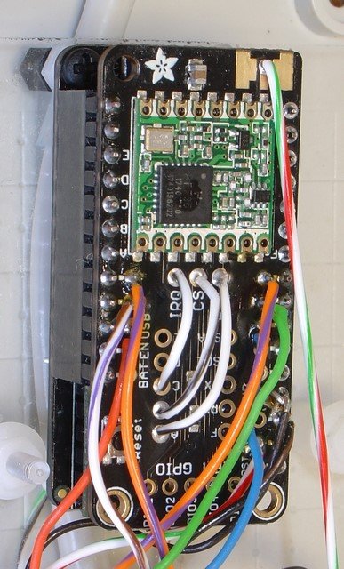
The pfodDesignerV3 will generate code for both the Adafruit Feather MO RFX9x LoRa board and for its recommended replacement the Teensy 3.2 + Adafruit Teensy Adaptor + Adafruit Radio Feather Wing. The diagram above shows how the Teensy pins are mapped to the Adafruit Radio Feather Wing.
Once you have finished this tutorial you will be able to design whatever menus you need to display, plot and log Arduino Data, Analog readings and Digital Inputs, and control Arduino outputs, PWM outputs and Digital Outputs via LoRa/Radio. In particular this tutorial will show you how to display, plot and log an Analog reading and display the state of a Digital input and control a PWM output and pulse a Digital Output. To actually switch something on and off see How to Add Relays to Arduino and Simple Home Automation for Beginners. There are also more pfodDesigner tutorials and another tutorial Data Logging and Plotting available.
The radio board used here is an Adafruit Feather M0 RFM9x LoRa board, 900Mhz or 433Mhz. You can also use other non-LoRa radio boards, but the LoRa version was chosen because it provides better range. Although an LoRa board is being used, this project does NOT set up a LoRaWAN network. Rather it is much simpler point-to-point connection which still provides 128 bit security without the complexity of a full LoRaWAN network.
NOTE: The Adafruit Feather M0
RFM9x LoRa board is NOT recommended. It is prone to lock up when
mains powered. When battery powered there is 2sec delay between
applying power and setup() being called. The recommended replacement
is a Teensy 3.2 + Adafruit Teensy Adaptor + Adafruit Radio Feather
Wing. See the Radio/LoRa
controlled Garage Door project for an example of using a Teensy
instead.
If you want to build a full LoRaWAN network, check out mbed's Intro to LoRa to get a feel for the registration and setup steps involved and then search Instructables for LoRaWAN and the internet in general, for projects.
This point-to-point project does not need any registration or gateways, etc. and so is much much simpler than a LoRaWAN setup. In this project all the custom code to control your remote device and to log and plot data from your Android is generated by the free pfodDesignerV3. The pfodApp on GooglePlay (~US$10) handles all the Android side and displays the control you designed and plots and logs the data you specified.
Since Android does not connect via radio directly, a simple ESP32 to LoRa bridge is used. You can connect to the ESP32 from pfodApp on your Android mobile via either WiFi, BLE or Classic Bluetooth. Arduino sketches are provide for each of these 3 types of connections. From the ESP32 there is a Serial connection to your radio/LoRa board which in turn connects to your remote LoRa board for control and data collection. You can use other boards like the ESP8266, instead of the ESP32, however the ESP32 is convenient to illustrate the WiFi, BLE and Classic Bluetooth connections, since it supports all three.
The LoRa/Radio connection is secured by a 128bit hash to protect against unauthorized control. See SipHash Secure Challenge and Response for the details on the security and see Reliable Remote Control via Radio/LoRa for how this is applied to the radio link. Encryption is not used. The messages are in clear text but the 128bit security guards against unauthorized connections and/or replay attacks. The pfodApp WiFi connection also supports 128bit security.
The pfodDesignerV3 generates all the high level Arduino code, but it needs a low level driver to configure the radio/LoRa module and to communicate with it. In this project the the low level radio support is provide by AirSpayce's Radiohead library. Only the lowest level RHGenericDriver part of the RadioHead library is used and is abstracted out via the pfodRHDriver class (see below) so it is simple to replace this support library with another one that supports the radio board you have.
2 off Adafruit Feather M0 RFM9x LoRa
900Mhz
or 433Mhz
boards ~ US$35 each
This document, LoRaWAN™
Regional Parameters, will help you decide which frequency you
should use for your country.
Note:
These boards are not recommend. Use Teensy 3.2 + Adafruit Teensy
Adaptor + Adafruit Radio Feather Wing instead. See Radio/LoRa
controlled Garage Door
2 off Antennas – either a short
length of wire (see
https://www.easycalculation.com/physics/electromagnetism/antenna-wavelength.php
for calculating the length)
OR 2 x uFL
SMT Antenna Connector + (900
Mhz Antenna and SMA
to uFL/u.FL/IPX/IPEX RF Adapter Cable) / 433Mhz
Antenna with cable ~ US$15 - $20
NOTE:
Always run with an antenna connected to avoid damage to the radio
module.
2 off 330 ohm resistors – Sparkfun ~ US$1
1 off Sparkfun ESP32 Thing ~ US$20
USB A to Micro B cable – ~ US$4 https://breadfruit/product/2008 (3 foot long) OR ~ US$3 https://www.adafruit.com/product/898 (6 inches long) OR ~ US$2 https://www.sparkfun.com/products/13244 (6 inches long) OR ~ US$5 https://www.sparkfun.com/products/10215 (6 foot long) OR similar
2 off USB power supply (500mA or more) – ~US$6 https://www.sparkfun.com/products/12890 OR ~US$7 https://www.adafruit.com/product/1994 OR similar
Arduino IDE V1.8.5 and a computer to run it on.
pfodApp on GooglePlay ~ US$10
pfodDesignerV3 on GooglePlay free and an Android Mobile V4.0+
This project is suitable for beginners, you need complete a few tasks before you start. You need to first set up the Arduino IDE, install pfodDesignerV3 on your Android Mobile and make sure you can transfer the final sketch (code file), that pfodDesignerV3 produces, from your mobile to your computer.
a) Install the Arduino IDE for your computer's
operating system from Getting
Started with Arduino and work through the example of compiling
and running the Blink example.
b) Install the free pfodDesignerV3
app on your Android mobile.
c) Check that you are able to
transfer files from your mobile to your computer either via a USB
cable or a file transfer app such as WiFi
File Transfer. See
pfodAppForAndroidGettingStarted.pdf
for more details.
The menu used here is the same one created in How to Display/Plot Arduino Data on Android
It has five (5) menu items, Analog reading scaled to real world units, On/Off monitor of a digital input, PWM Output control, On/Off Setting to set or pulse a digital output and Chart to plot an analog reading scaled to real world units.
Each of these items offers designable text, formats and displays. But first you need to open pfodDesignerV3 and create a new menu.
Download and install pfodDesignerV3 from GooglePlay.
On opening pfodDesignerV3 you will be presented with the Start new Menu button. Each screen also has a Help button.
Click Start new Menu
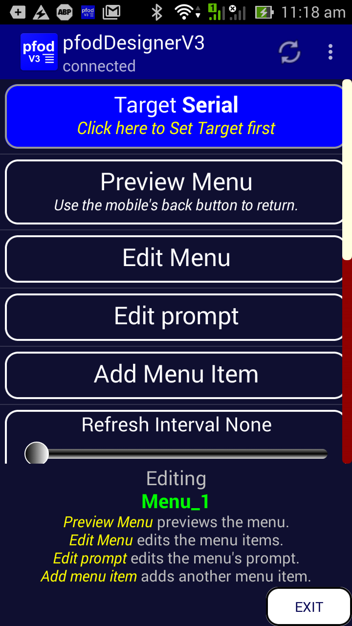
and then click the Target .. button.
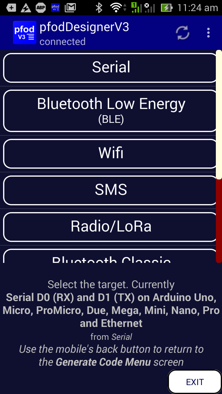
and choose Radio/LoRa and then choose the Teensy (or Adafruit LoRa) as the target.
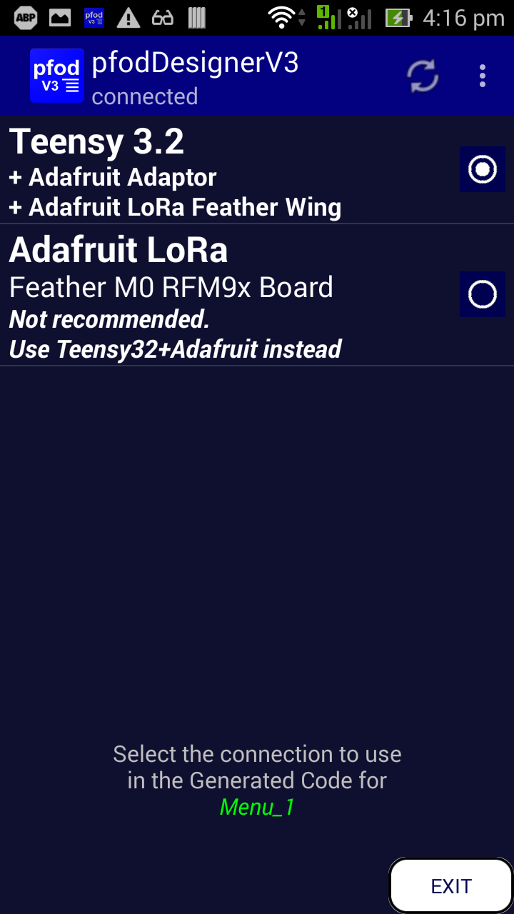
Use the mobile's back button to get back to the Editing Menu_1 screen with the Target Teensy LoRa set.
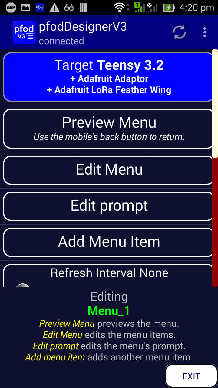
Continue on with Setting the Refresh Interval in the tutorial, to complete the menu and plot design.
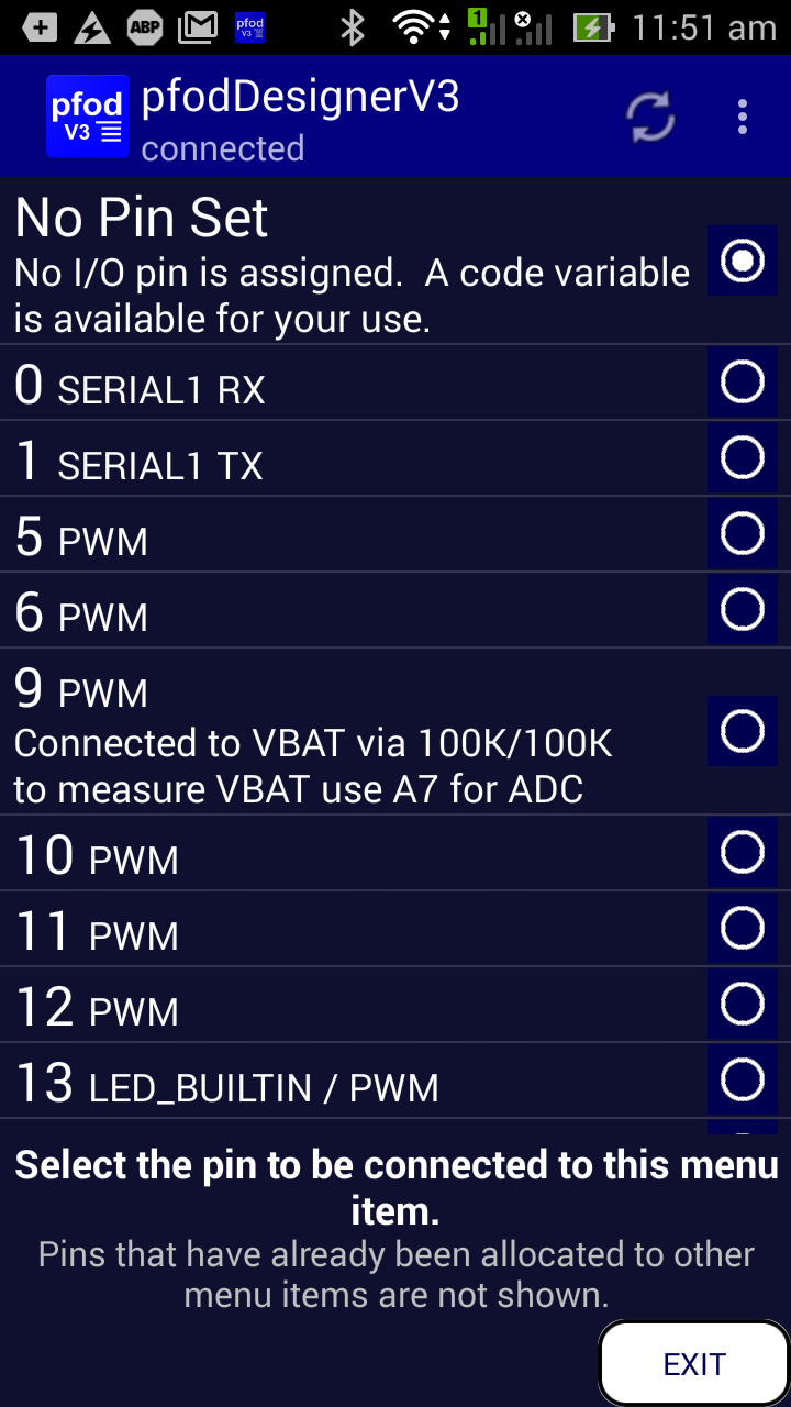
On both the Teensy/LoRa Wing and the Adafruit Feather M0 RFM9x LoRa board, pin 4 is not available, so when working through the How to Display/Plot Arduino Data on Android tutorial you will need to choose another input for the “Door is” Open/Closed input. In this example pin 6 was used. Also when using the Teensy/LoRa Wing, D13 is used to control the radio module and so cannot be used to control the Teensy board LED. In this case pin 3 was used.
On the Teensy connected to the Adafruit Radio Feather
Wing, not all the pins are available/accessible. Teensy pins 9,10 and
4 are used to control the Radio module via the A,B,C wiring on the
Adafruit Radio Feather board and pins 11,12,13 are used to
communicate with the Radio module via SPI.
Note: this
means you cannot drive the Teensy board LED as pin 13 is use for the
SPI SCK.


On the Adafruit Feather M0 RFM9x LoRa board pin 4, and others, are not available, as they are used by the radio module, and so are not displayed as one of the options when choosing a Digital I/O pin.
When you have finished the menu design, leave the Target as Teensy 3.2 + Adaptor + LoRa Wing and click Generate Code button in the the Generate Code Menu.
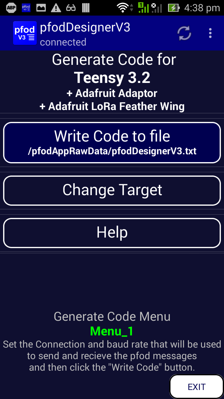
and transfer
the resulting code to your computer as described in Transferring
the Sketch to Your Computer part of the tutorial.
The
generated sketch for Teensy is here. (The Adafruit Feather M0
RFM9x LoRa target sketch is here)
Note: Select Teensy 3.2 (or Adafruit
Feather M0 for the Adafruit Feather M0 RFM9x LoRa)
as the board when compiling these
sketches
You also need to install the pfodParser
library to add the pfodSecurity and pfodRadio support and the
AirSpayce's
Radiohead library for the low level radio driver
libraries.zip contains
the libraries need for thess sketchs
The
generated sketch (Teensyt_LoRa_DataServer.ino) for the Teensy 3.2
+ Adafruit Adaptor + Adafruit Feather Radio Wing board has a
frequency of 915Mhz, a server address of 0x68 and no security
password.
You should set a security password and also set the
frequency to suit the board and your country.
// the server address for clients to connect to
const uint8_t NODE_ID = 0x68; // this node's address can be any address from 1 to 0xff,  the server address for clients to connect to

// Change to 434.0 or other frequency, must match the RX's, pfodServer's, freq!  AND must match the range allowed in your country.
#define RF95_FREQ 915.0
// == 81.9mm length wire for 1/4 wave length antenna, see https://www.easycalculation.com/physics/electromagnetism/antenna-wavelength.php

// add your pfod Password here for 128bit security
// eg "b0Ux9akSiwKkwCtcnjTnpWp" but generate your own key, "" means no pfod password
#define pfodSecurityCode ""
// see http://www.forward.com.au/pfod/ArduinoWiFi_simple_pfodDevice/index.html for more information and an example
// and QR image key generator.
NOTE: Always run with an antenna connected to avoid damage to the radio module.
Note: The Adafruit Feather LoRa Wing radio module
needs to be wired for use with the Teensy 3.2 Adafruit Adaptor board
as shown here
RST to A, CS to B and IRQ to C

Compile and Upload the sketch to the Teensy
3.2/Adafruit LoRa Wing stack.
That is the pfodServer (pfodDevice)
done, but to connect you need another matching LoRa board.

The Android to Radio Bridge consists of two parts:- an LoRa pfod client node to connect to the LoRa pfod Server above and a WiFi, BLE or Bluetooth pfod bridge server for the Android mobile to connect to. The pfod bridge server is connected to the LoRA pfod client node via a hardware UART connection between the two boards.
Here an Adafruit M0 LoRa Feather board is used as the pfod client (see below for how to overcome the occasional Adafruit M0 LoRa Feather board lockups).
The client
node code is here (Adafruit_LoRa_ClientBridge.ino). This client
code has an address of 0x38 and is configured to connect a server
with address 0x68.
You need to make sure RF95_FREQ matches.
Tip: Open an second instance of the Arduino IDE to compile and load the client code. That way you can have two Arduino Serial monitors running at the same time to see output from each end of the link.
For initial testing, you can drive the radio link from the Arduino Serial Monitor without using the ESP32 bridge board. At the top of the Adafruit_LoRa_ClientBridge.ino sketch
// uncomment the following line to send cmds / receive responses via USB Serial
#define DEBUG_SEND_VIA_USB
This redirects the I/O to the USB instead to the UART which will be connect to the ESP32.
Here is a sample connection. First enter {.} to get the main menu and then enter {D`1} to turn the Led on. In between the client will send keepAlive cmds, { }, keep the link open. Each time the server receives a command it first sends back its buffered plot data and then sends back the response. Since the client is listening for the response there is no radio Tx-Tx conflict.

When you have finished this testing, comment out the #define DEBUG_SEND_VIA_USB line again and reprogram the client board in preparation for adding the ESP32 bridge.
Here an ESP32 is being used as the bridge to the LoRa client. You can use other boards, but the ESP32 is convenient to illustrate WiFi, BLE and Classic Bluetooth connections as it supports all three. Here a WiFi connection was used, but code is given below for ESP32 BLE and Bluetooth pfod bridge servers if you want to use one of those instead.
Wire up the ESP32 board to the Adafruit Feather LoRa board as shown in this circuit diagram (pdf version). Note: the Adafruit Feather LoRa is prone to lock up when mains powered. This circuit has a reset push button to clear the lock ups. The Adafruit Feather LoRa board is only being used here because three were already purchased.


The USB power connection to the Adafruit M0 LoRa board supplies 3V3 to both boards and the momentary push button disables the regulator forcing both boards to power cycle. The 330R resistors protect against miss connecting TX/RX wires.
Note: The Adafruit LoRa board also locks up
sometimes when power is applied. Pressing the board's reset push
button does not fix the lockup. The manual momentary push button,
shown here, between EN and GND pins can be used to clear any lockups
that occur.
The
Sparkfun ESP32 Things also sometimes fails to register itself on the
WiFi network on power up. The manual push button solves that problem
also.
The ESP32 board can be programmed to be connected to via either WiFi or BLE or Classic Bluetooth. pfodApp supports all of these types of connection so it is up to you which you choose. pfodApp WiFi connections offer the option of 128bit security, like the LoRa/Radio connection. However these links are completely separate and you can set different passwords for the WiFi and Radio links or omit the password for either link.
Programming the ESP32 requires extra Arduino setup. See the tutorial on ESP32 Code Generator for pfodApp for the details on how to setup Arduino to program the ESP32 and the extra libraries needed.
See Debugging the Bridge connection, below, for how to view the messages flowing through the bridge.
To setup a ESP32 WiFi to Radio/LoRa bridge, use this sketch, pfodESP32_WiFi_Bridge.ino Edit the sketch to fill in your network SSID and password and set a static IP for this ESP32 to connect to. You can (should) also add a security password and enter the same password when setting up the connection in pfodApp. See Secret Key Generator for Secure Challenge and Response for a simple way to create a password and a QR code for it.
Then to connect, install pfodApp from GooglePlay and set up a connection for the ESP32 board, as described in pfodAppForAndroidGettingStarted.pdf.
On connecting to the ESP32, pfodApp will display the menu you designed for the LoRa board.

Now you click the LED button to turn the led on for 10sec and then turn off. The menu will update to LED is Off when the led turns off. If you connect the D6 input to GND then the menu will show Door is Closed.
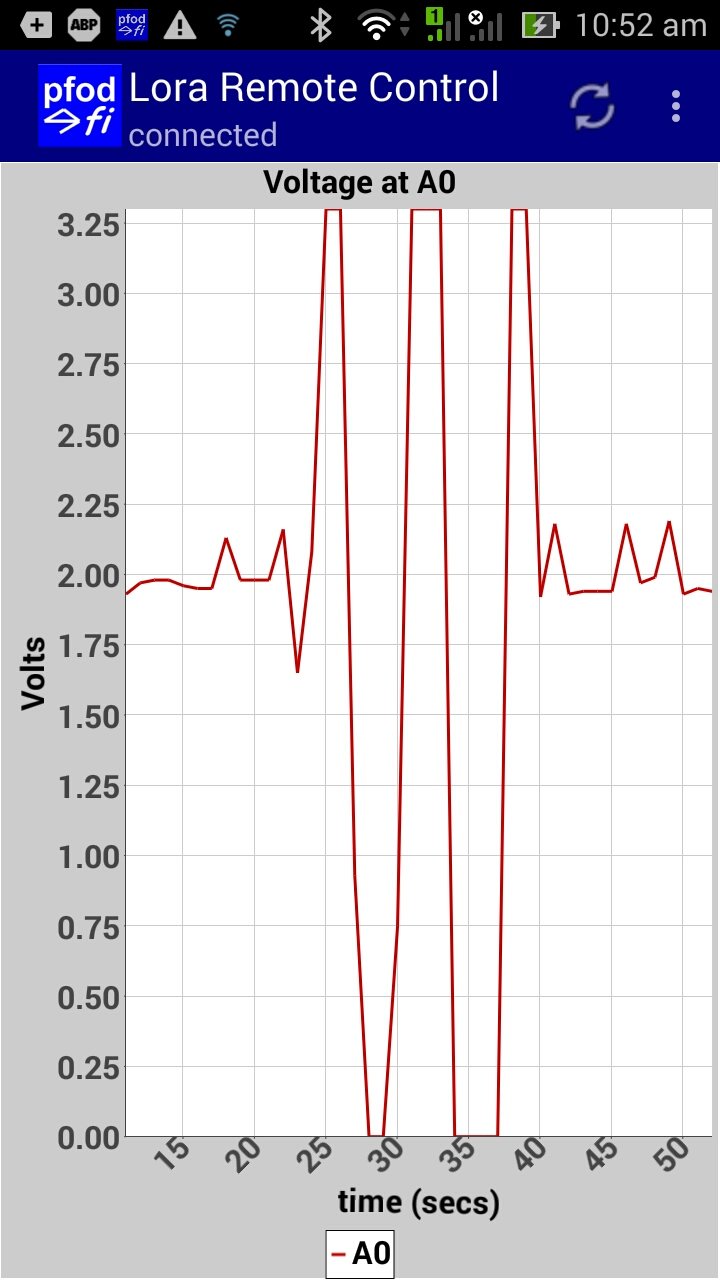
The plot will also show the varying voltage measured at A0.

You can use two fingers to zoom in to get a closer look at part of the plot. See pfodAppForAndroidGettingStarted.pdf for the plot controls.
You can use the PWM slider to control the input voltage to A0. Connect a 47K resistor from D5 to A0 and connect a 470nF capacitor from A0 to GND (Note: If the capacitor you are using has a +/- make sure the – is connect to GND). This RC network smooths out the PWM pulses to give an approximately steady DC voltage. Then as you adjust the PWM slider the voltage measured at A0 changes and the menu shows the changed value. See the How to Display/Plot Arduino Data on Android tutorial.
If you look at the pfodApp's Debug View accessed from your mobile's menu you will see the menu update messages are very short because pfodApp caches the menu and there after the Arduino sketch only send the update values for each menu item instead of resending the whole menu text each second. If you look at the pfodApp's Raw Data view, you will see the CSV data records that are being sent and logged. This is where the plot gets its data from. The two ,, on the end of each record are place holders for plot 2 and plot 3's data which were not used in this example.
pfodApp automatically saves the plot data on your Android mobile under the directory /pfodAppRawData, in a file with the same name as the connection, with any spaces replaced with _. For example if the connection you created in pfodApp to connect to the ESP32 was named by you as “LoRa Remote Control” then the plot data is saved in the file /pfodAppRawData/LoRa_Remote_Control.txt
The name of the raw data file is also displayed by pfodApp as you exit the app. You can transfer this plot data file to your computer for further processing.
To connect to your Radio/LoRa device via BLE from pfodApp on your Android mobile. Program the ESP32 with the pfodESP32_BLE_Bridge.ino sketch and then set up a BLE connection in pfodApp as described in pfodAppForAndroidGettingStarted.pdf.
To connect to your Radio/LoRa device via Bluetooth from pfodApp on your Android mobile. Program the ESP32 with the pfodESP32_Bluetooth_Bridge.ino sketch and then set up a Bluetooth connection in pfodApp as described in pfodAppForAndroidGettingStarted.pdf.
To see the command and responses and rawData flowing through the bridge, you can uncomment the #define DEBUG at the top of pfodESP32_WiFi_Bridge.ino sketch and then monitor the traffic on the Arduino's Serial Monitor.
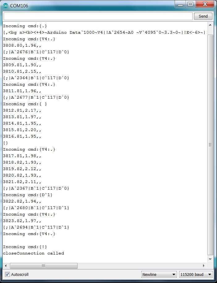
The menu has a 1sec re-request, but when you switch away from pfodApp on your mobile, when you open the Voltage Plot, pfodApp automatically sends keepAlive cmds, { }, every 5 sec to keep the link open. When you close pfodApp, it send the closeConnection command, {!}, to shut down both links.
This completes the tutorial. The pfodDesignerV3 tutorials provide more examples of using pfodDesigner and Simple Home Automation for Beginners looks at attaching relays, so that you can switch real things on and off. You can also create you own custom control with pfodApp. See the tutorials under Custom Arduino Controls and check out the full pfodSpecification.pdf
For a complete Radio remote control project, using the Teensy 3.2/Adafruit Feather LoRa Wing stack, see the Radio/LoRa controlled Garage Door project
AndroidTM is a trademark of Google Inc. For use of the Arduino name see http://arduino.cc/en/Main/FAQ
The General Purpose Android/Arduino Control App.
pfodDevice™ and pfodApp™ are trade marks of Forward Computing and Control Pty. Ltd.
Contact Forward Computing and Control by
©Copyright 1996-2024 Forward Computing and Control Pty. Ltd.
ACN 003 669 994