
|
Home
| pfodApps/pfodDevices
| WebStringTemplates
| Java/J2EE
| Unix
| Torches
| Superannuation
|
| About
Us
|
|
|
3G/2G SMS Remote Control (Arduino/pfodApp)
|
by Matthew Ford 6th July 2018 (original
6th July 2018)
© Forward Computing and Control
Pty. Ltd. NSW Australia
All rights reserved.


This tutorial uses Adafruit FONA 3G SIM5320 Cellular breakout board (European or American versions), which also connects to the older 2G networks, and Arduino Mega2560 and pfodApp to control devices via SMS. All Arduino code is generated by the free pfodDesigner. No Arduino coding is required. The pfodApp handles all the Android side. No Android coding is required.
As a complete example project, an SMS remote controlled hot water service is described.
It is Reliable – commands are always responded
to and lost messages are re-requested
It is Secure – uses
128 bit password protection
It handles non-English characters via
UTF-8
Its messages are compact. pfod messages are small and menus
are cached to reduce data transfer.
It does not require any third
party web service accounts – It only needs an active SIM card
(without a pin)
It is Customizable – you can use
pfodDesignerV3 to create you own custom menu
It is Easy –
the pfodDesigner generates all the Arduino code. pfodApp handles all
the Android side. You don't need to do any coding.
It is Flexible
– all the pfod screens are available via SMS, like sub-menus,
multi and single selection list, text input, data logging and
plotting.
See pfodSMS
message design for how the SMS connection is made reliable.
See
Challenge
and Response Security for Internet connected pfodDevices for the
details of the 128bit security.
See pfodDesignerV3,
Android / Arduino menus made Simple for details on the designing
your own custom menu.
See the pfodSpecification.pdf
for the details of all the pfod messages and screens.
The previous 2G version of this project is here.
Here is a the basic 3G Adafruit FONA SIM5320 SMS set up. 2G is being replaced by 3G in may places. This board, SIM5320, will connect to the older 2G networks and then continue to work when they are replaced with 3G.
SIM5320A is meant to be used for American market. SIM5320E is meant to be used for European market. SIM5320J is reported to be for the Australian market but SIM5320E (Adafruit FONA European Version) works fine on the Australian Optus network. (If you want an SIM5320J board search Aliexpress SIM5320J for it.)

Before you start you need to charge the Lithium Ion battery. This battery supplies the peak current (up to 2A) needed to run SIM5320.
The Pwr Key turns the SIM5320 on and off. Before you start plug in the Lithium Ion battery into the Adafruit FONA and plug in a Micro USB cable to a charger. The battery should start charging (Yellow led on) and the SIM5320 should be off. If the SIM5320 power light comes on, press the Pwr Key for 5sec and release to turn it off. Once the battery is charged the Green led will come on. This can take some hours. Then disconnect the battery being careful to NOT pull on the wires but lever out the white connecting plug.
This only uses 4 wires. Power (+5V and GND) and
Serial1 (TX1 and RX1). Connecting the Mega2560 USB to your computer
lets you both power the circuit and program and debug it.
(The
pfodSMS_SIM5320 library also supports connecting the Rst, Key and PS
lines but they are not necessary.)
Connect the Vio pin to the 5V pin. This sets the I/O voltage levels to match the Mega2560 5V I/O. Then wire the 5V and Gnd pins to the Meg5260 5V and GND and wire the SIM5320 TX pin to the Mega2560 RX1 (pin 19) and wire the SIM5320 RX pin to the Mega2560 TX1 (pin 18).
Having wired the SIM5320 to the Mega2560 as described above, plug in the battery and then connect the Mega2560 USB to your computer. Turn on the SIM5320 (no need to have a SIM inserted at this stage) by pressing the Pwr Key for 5sec and then releasing it. The red power led will light up. The SIM5320 remembers this setting so next time you supply 5V either via the Mega2560's USB, or the Micro USB on the SIM5320 board, the SIM5320 will power up.
If you power cycle the SIM5320, press the Mega2560
reset push button once afterwards. If you apply power and the SIM5320
does not automatically power up, i.e. no Green and Red leds showing,
press the KEY pushbutton for 5 sec to power the SIM5320 on. Then
reset the Mega2560, via its reset pushbutton.
OR
you can
connect up the SIM5320 power reset/status and system reset pins to
digital inputs on the Mega2560 and pass those input numbers in the
init(.. ) method (see the init() method in the pfodSMS_SIM5320.h
file).
When the SIM5320 is powered via a USB connection, either to the Mega2560 or to the SIM5320 board, the battery shows as charging (yellow). However when the SIM5320 is powered down the battery shows as charged (green).
The default SIM5230 baud rate is 115200. The sketches generated by pfodDesignerV3 use a baud rate of 19200 so you need to change the SIM5320's default baud rate to suit.
Having wired up the SIM5320 to the Mega2560 and powered it up via the Mega2560's USB connected to your computer (as described above), open the Arduino IDE and load the pfodSIM5320SetBaudRate.ino sketch and program the Mega2560 and then open the Arduino's Serial Monitor to see the output.
After counting down for 10secs, the sketch will prompt to you make sure the SIM5320 is powered up and then ask you to enter any character to continue. The program will then connect to the SIM5320 at 115200 baud and change the power on baud rate to 19200 and check that the change worked.
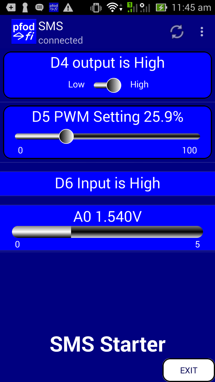
pfodDesignerV3 allows you to create menus to turn outputs on and off, control PWM, read Analog and Digital inputs and more and then generate the Arduino code for Bluetooth, BLE, Wifi/Ethernet and SMS. The pfodParser library includes an example sketch, pfodSMS_SIM5320.ino, for controlling and reading data from the Mega2560 via the SIM5320 and pfodApp.
Download the pfodParser.zip file and install the pfodParser library in your Arduino IDE (using the menu options Sketch → Include Library → Add .ZIP Library). Then open the pfodSMS_SIM5320.ino example under Examples → pfodParser.
With the SIM5320 wired up to the Mega2560 and with a SIM card inserted (NOT pin protected) and the battery connected. Connect the Mega2560 to your computer and upload the pfodSMS_SIM5320.ino sketch. Check the SIM5320 is powered up. If not press the Pwr Key for 5secs and release. Wait 30 secs for the sketch to get through its startup sequence.
Install pfodApp from Google Play on your Android phone. Open pfodApp and create an SMS connection to phone number of the SIM card you inserted in the SIM5320 (see pfodAppForAndroidGettingStarted.pdf for the details)
Open the connection and pfodApp will send an SMS message to connect and request the menu above. Once the menu is displayed you can turn D4 on and off and change the PWM output of D5 as well as see the setting of Input D5 and the value of A0.
The first thing to realize is that SMS is sloooow and may not get there at all or arrive out of order. So when you connect with pfodApp there will be some delay before there is an SMS response. If the message got lost or delayed, pfodApp will automatically resend it after 3mins. After 5 such retries the pfodApp will tell you the connection is lost. You can adjust the 3mins time in the pfodApp's connection edit screen.
By default each time you send a command, or refresh the menu, pfodApp prompts you to confirm you want to send a SMS message.
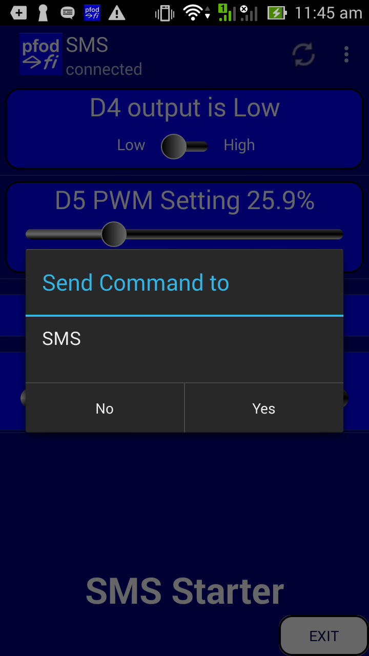
You can disable this confirmation question in the connection setup screen by unticking the Confirm Menu Selections option
Long menus are sent via multiple SMS messages which take longer to arrive. If you have a long menu, the sms connection code in the pfodParser library handles all of this for you. As well as this pfodApp caches the menu so that after the first connection only the shorter updates are sent.
To prevent someone else controlling your remote device, you should add a secret key to the sketch and include it in the password section of pfodApp's connection.
In the sketch change the line
#define
pfodSecurityCode ""
to add your own secret
key (up to 32 hex digits, 0..9 A..F) e.g.
#define
pfodSecurityCode "b0Ux9akSiwKkwCtcnjTnpWp"
You can use the Secret Key Generator to generate you own random 128bit key and also generate a QR image that you can scan with the pfodApp Scan QR button to easily insert the secret key into the SMS connection setup.


For all the details on pfodApp security see SipHash Secure Challenge and Response and see Reliable Remote Control via SMS for the design of the pfod SMS messages. The pfodSpecification.pdf describes all the menu and control messages used by pfodApp.
The pfodDesignerV2 generates code that works, but you may want to debug your own extra code or look at what is happening while the GPRS shield is trying to connect to the network or when it is receiving SMS messages.
If you are not getting a response from the messages that pfodApp is sending to your SIM5320 board, you can enable debugging by uncommenting these lines in setup()
Serial.begin(19200);
pfodSMS.setDebugStream(&Serial);
There are also #define DEBUG... lines at the top of the pfodSMS_SIM5320.cpp library file that control what debug messages are produced. Then connecting the Mega2560 to your computer, and so powering the boards from its 5v supply, the Arduino Serial Monitor will display the debug output.
If you are debugging your own code, i.e. the how the pfod messages are handled in your sketch, you can just connect the parser to the USB Serial and then test the pfod messages from the Arduino terminal. i.e. change the setup() from
parser.connect(&pfodSMS,F(pfodSecurityCode)); // connect parser to SMS stream
to
Serial.begin(19200);
parser.connect(&Serial);
// connect parser to USB Serial
//
parser.connect(&pfodSMS,F(pfodSecurityCode)); // connect parser
to SMS stream
Then from the Arduino terminal you can type in {.} to get the Mega to return the main menu and then send back command you want to execute, e.g. {A`1} to turn the relay on and {A`0} to turn it off. (The pfodApp usually sends these messages for you when you click the slider.) Then add extra debugging parser.println() to monitor what extra code you added is doing.
A remote control for a hot water heater will be used as a complete example 3G SMS control project. This lets you turn the hot water heater on and off via SMS and also check if it is currently on or off.
Here is a quick start guide to building your own SMS hot water control.
Purchase the parts on this list.
Install the Arduino IDE version 1.8.2 and download and install the pfodParser library.
Download the free pfodDesignerV3
Design your custom menu to turn a digital input on and off from a menu slider on your Android mobile. Here is the generated code, SMS_HotWater_control.ino
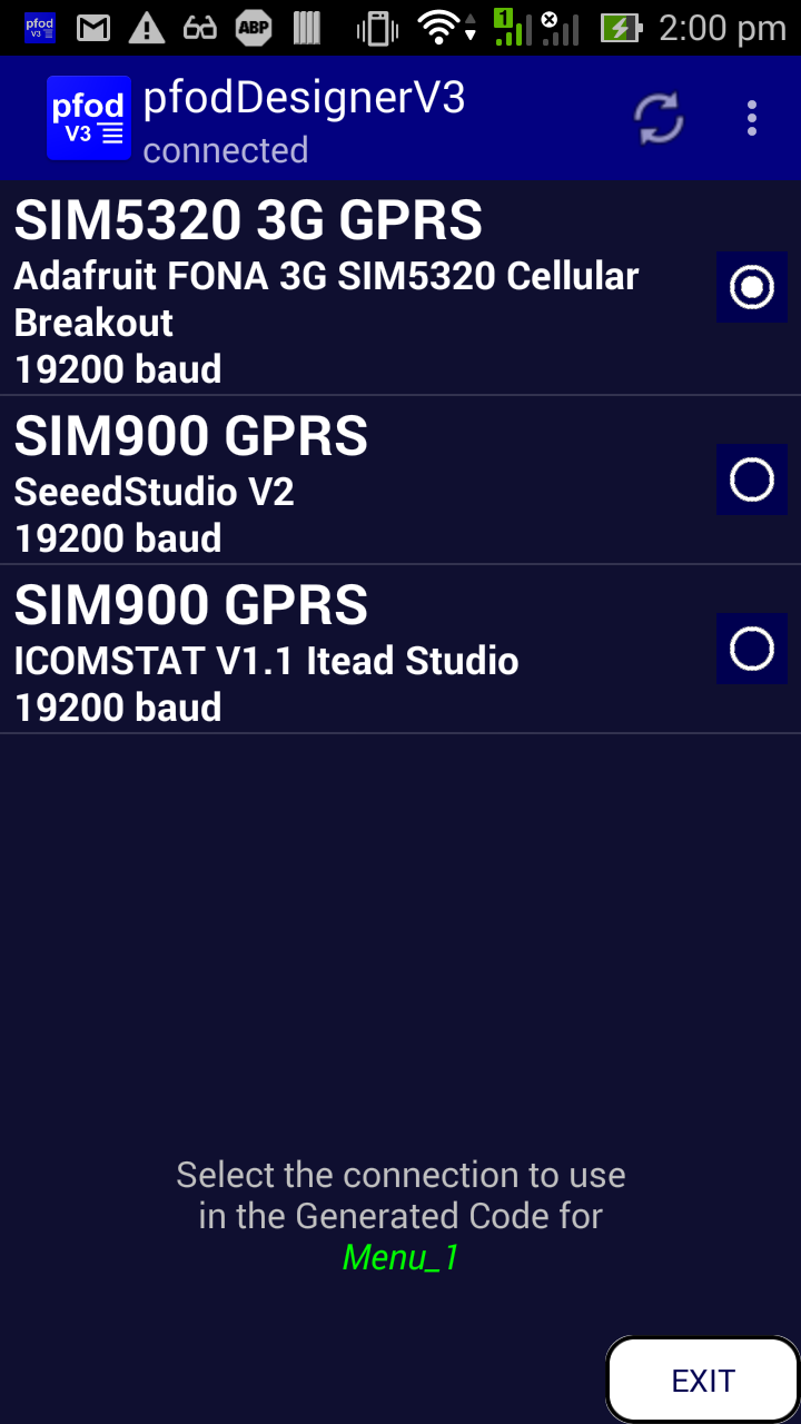
Generate the code, selecting Adafruit FONA 3G SIM5320 as the target.
Wire up the Adafruit FONA 3G SIM5320 to the Mega2560 and install the SIM and battery, as described above, and run the pfodSIM5320SetBaudRate.ino sketch to set the SIM5320 baud rate to 19200.
Transfer the generated code from your mobile to the IDE (see the pfodAppForAndroidGettingStarted.pdf for details), add your secret password, compile and download to the Arduino Mega 2560.
Connect the digital output from the Mega2560 to the solid state, or normal relay, between D8 and GND (or which ever pin you chose in the pfodDesignerV3). See How to Add Relays to Arduino for more details on relays.
Apply USB power to the Mega. The Mega2650 supplies power to the SIM5320.
Install pfodApp on your Android mobile and set up an SMS connection to the SIM5320's phone no. (see the pfodAppForAndroidGettingStarted.pdf for details). Set the password for the connection if you added one.
Connect and see your custom menu displayed via SMS. Click the button to turn the relay on or off.
Finish wiring up the mains wiring and USB power supply and mount in an insulated box. Get your electrician to wire the relay in to your Hot Water circuit.
The free pfodDesignerV3 app will generate all the code you need to turn the solid state or some other relay on and off, but the SMS connection in the pfodParser library supports all the pfod screens so once you get started you can add sub-menus, numeric sliders, multi-text sliders, text input screens, data logging and plotting using pfodDesignerV3 and control them via SMS. Check out the various tutorials on using pfodDesigner. Also check out the pfodSpecification.pdf for all the screens and messages supported.
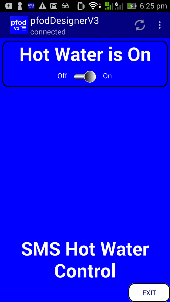
The above is a WYSIWYG display of a Hot Water control in the pfodDesignerV3. The Arduino code generated by pfodDesignerV3 for this design is in SMS_HotWater_control.ino You can load that into your Arduino IDE and program the Mega2560.
To make your own design using the pfodDesignerV3, start a new menu and click on the “Target Serial” button at the top to change the target and then choose SMS and then SIM5320 as the target.
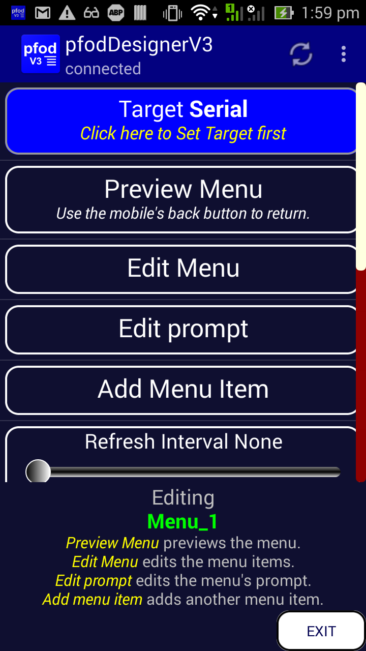

Then use the mobile's back button to get back to the Editing Menu screen from which you can edit the prompt and add menu items. Follow the tutorial Design a Custom menu to turn the Arduino Led on and off steps but set your own prompt text and set D8 as the output pin connected to the On/Off menu item.
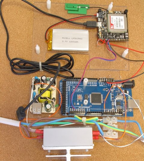
Here are the components mounted on the two mounting plates with the Solid State relay wired in.
The mains powered USB supply board is taken from a dis-assembled 1A Sparkfun USB supply (https://www.sparkfun.com/products/11456).
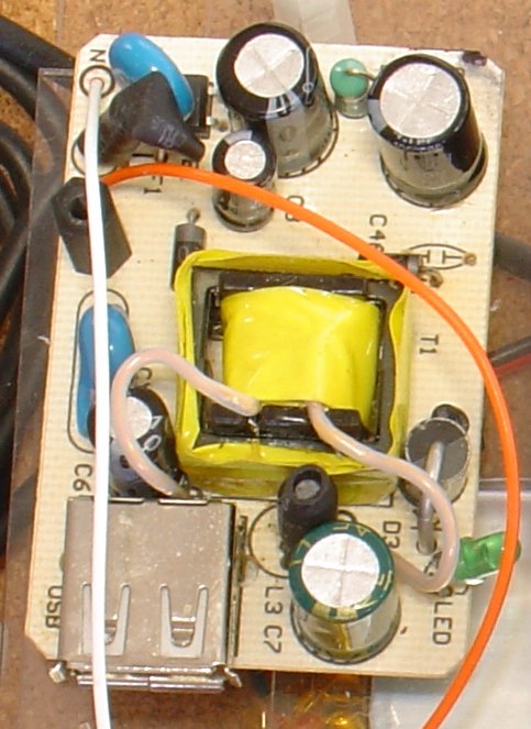
Two 2.5mm mounting holes were drilled in the USB supply board were there were no tracks and nylon 2.5mm stand offs used to mount the board. The Active and Neutral connections were then wired to the incoming mains.
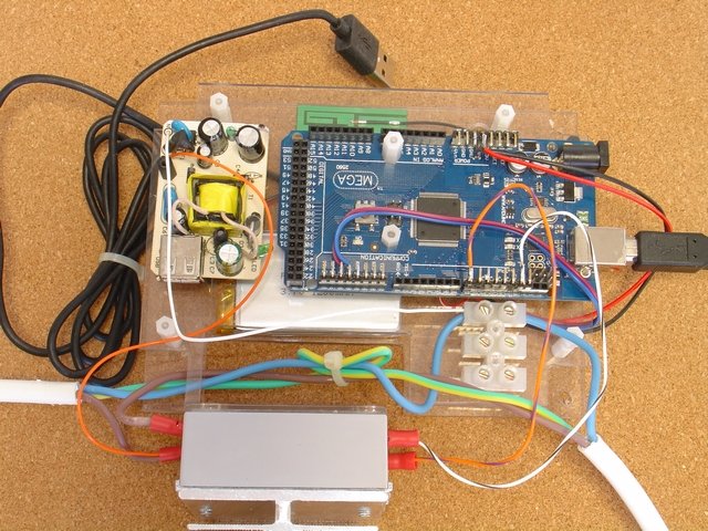
Here are the boards stacked ready to mount in the enclosure. Note: the mains powered USB supply is unplugged and the Mega2560 USB is connected to the computer for safe programming and testing without any mains power applied.
There are many versions solid state relay available. Make sure you purchase on that can handle the current and voltage of your heater and can be controlled by 5V dc and a few milliamps available from the Arduino output pin. The one used here, FOTEK SSR-40 DA, switches up to 380VAC at 40Amps and is controlled by any thing more then 3V dc and takes less than 7mA.
You must use a heat sink and you must apply a THIN smear of heat sink compound or thermal grease on the back of the solid state relay before bolting it to the heat sink. The idea is to completely cover the surface with the thinnest layer of head sink compound to fill in the microscopic valleys in the metal's surface. When turned on the solid state switch drops 1.6V which generates 16Watts of heat at 10Amps. The heat sink is need to get rid of this heat so it needs to be mounted in free air not inside a plastic box. So a slot is cut in the box to allow the heat sink to protrude.

The small slot in the lid engages with the heat sink to prevent side to side movement. The cut out in the components mounting boards keeps the Solid State Relay tight up against the side of the enclosure. The large cutout in the enclosure is a little smaller then the Solid State Relay.
The GPRS shield delivers SMS messages via the Serial1
connection at any time and your main loop() must call
cmd
= parser.parse();
often to process the Serial1
data before the 64byte buffer in the Arduino library code fills up
and data is lost.
So you must keep your main loop() running quickly.
You should never use delay() and should check that none of the
libraries you are using have delays in them. Using 19200 baud rate of
the SIM5320 via Hardware Serial1, I have not found it necessary to
increase the buffer size in the Arduino library code. However you can
increase the Arduino buffer size, if you wish, by modifying the
define in the Arduino
….\arduino-1.8.3\hardware\arduino\avr\cores\arduino\HardwareSerial.h
from
#define SERIAL_BUFFER_SIZE 64
to
#define
SERIAL_BUFFER_SIZE 128
However if I enabled a lot of debugging output, as described above, you need to have a fast baud rate for the Arduino Serial Monitor otherwise the delay introduced by send debug messages to the terminal caused parts of the SMS messages to be missed.
The example project above just displays is the how water is on or off and allows you to switch it but the SMS connection handles all of the pfod messages (see pfodSpecification.pdf )
If you add temperature sensor to your arduino you can also monitor the temperature and send back readings at regular intervals. Sending back a data reading is the same for bluetooth, wifi or SMS. See Data Logging and Plotting for more details and examples of data logging and plotting.
When the pfodSMS library sees the new line from println(), it will send the raw data as an SMS. On your mobile, just leave pfodApp running in the background and your your mobile will notify you when an SMS is received. Open pfodApp again to bring it to the front and then open the Raw Data screen from the mobile's menu to see the data. Note: The pfodSMS messages are UTF-8 characters together with connection and message numbers, encode using a Base64 encoding so they don't look like normal text. See pfodSMS message design for all the details.
AndroidTM is a trademark of Google Inc. For use of the Arduino name see http://arduino.cc/en/Main/FAQ
The General Purpose Android/Arduino Control App.
pfodDevice™ and pfodApp™ are trade marks of Forward Computing and Control Pty. Ltd.

Contact Forward Computing and Control by
©Copyright 1996-2020 Forward Computing and Control Pty. Ltd.
ACN 003 669 994