|
Home
| pfodApps/pfodDevices
| WebStringTemplates
| Java/J2EE
| Unix
| Torches
| Superannuation
|
| About
Us
|

|
pfodDesignerV2™
|
by Matthew Ford 10th September 2014
©
Forward Computing and Control Pty. Ltd. NSW Australia
All rights
reserved.


This tutorial is aimed at the absolute beginner. If you can handle a sharp knife without cutting your fingers off you can make and customize this home automation controller.
Safety
Warning – This tutorial is for beginners and only covers
switching low voltage devices.
110V/240V Mains power is lethal.
Any wiring to the mains power should only be done by a qualified
electrician.
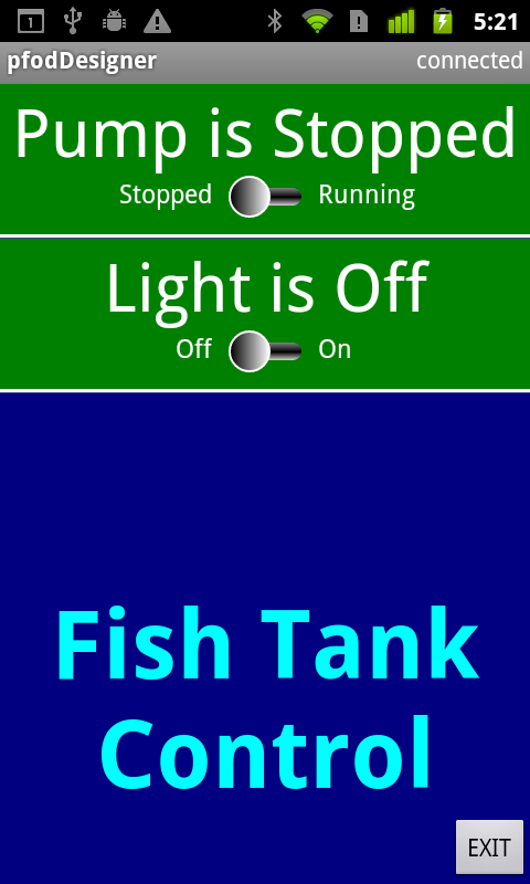
This tutorial first goes through the steps required to switch low voltage devices on and off from a custom menu on your Android mobile without needing to do any coding or any soldering. It then gives a detailed construction example by completing the Fish Tank control started in the previous tutorial.
This is Home Automation for Beginners so it only deals with switching low voltage devices, I.e devices supplied by low voltage power packs, but that covers many devices in the home. Led lighting, for example, is often (but not always) powered by a low voltage power pack.
Both the Led fish tank light and the pump are powered by low voltage power packs and so are suitable for complete beginners to control.
The
previous tutorial, Design
Custom menus to switch Arduino outputs on and off, has already
covered using the free pfodDesignerV2 to create your own custom Android
menu to switch things on and off. In that tutorial we used
pfodDesignerV2 to generate all the Arduino code needed to show the menu
on your Android mobile, via pfodApp, and to switch Arduino outputs on
and off.
To
complete the example Fish Tank controller's construction you need to
add a relay shield, wire up the low voltage power cables to the
relays and put everything in a box.
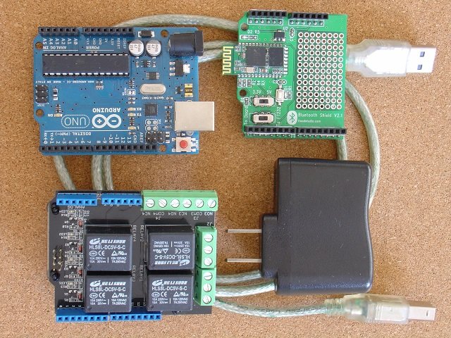
Here
are the boards and power supply you need, including the relay shield,
and, on the right, the box and tools needed to mount the
controller.
This is the parts
list for the boards. To mount the controller you need a plastic
box, a sharp knife (you can use a sharp kitchen knife but the craft
knife show above is easier to handle), some files, two tie wraps,
some double sided tape, a small screw driver and an insulated screw
terminal (the type used for joining power wiring will do).
The box I am using here is bigger then it needs to be and has a clear plastic lid, but it was what I had on hand. The insulated screw terminal is only needed if your low voltage power cable is a round one with copper brad covering a central core. (see below for an example)
Using
the files, make small slots in one side of the plastic lid to allow
entry for the USB cable from the USB power pack and the low voltage
power leads of the devices you are switching. Here I am going to put
both low voltage power leads through the one hole.
When
we are finished we will stick the stack of boards to the lid using
the double sided tape.
To switch the Pump you need to put relay 4 into the its low voltage power circuit. For this you need the sharp knife. First separate the low voltage twin flex as shown here.
Then
cut one of the wires and carefully strip back the insulation of the
two ends. Taking care not to cut the wires. Always push the knife
away from you so that when it slips you will not have to rush to
hospital for an expensive tendon operation on your hand.
Then
unscrew the NO4 (normally open) and COM4 (common) terminals for relay
4 (J4) and insert the wires you have just bared and screw up the
terminals.
That's
the pump done.
The Led Light has a round low voltage power cable, so wiring it up is a little different. Cut the cable completely through and then carefully strip back the outer insulation to expose the copper brad and the inner core. Do this to both ends and then twist the copper brad all together and secure it in the insulated screw terminal.

Then
strip back the inner cores and wire them to theNO3 and COM3
terminals.
That's it finished.

Plug in the USB Power Pack and plug the USB cable into it. Now you can connect from your Android mobile using pfodApp and turn the Pump and light on and off. You will be able to hear the relays switch on and off as you press the two menu buttons. (No need to slide the slider, just click anywhere in the button.)
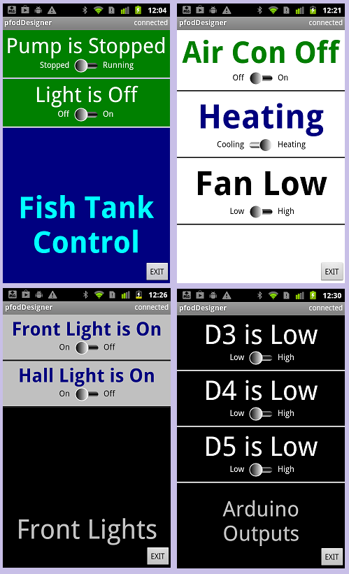
Using the pfodDesignerV2 you can create your own Android menus to switch up to 4 devices on and off using these relays. The pfodApp can have multiple connections defined so you can use the same pfodApp to control multiple boxes.
This tutorial generated all the necessary code for you. You can use the generated code as a starting point for your own extensions. For example one user added a timer so that once the pump was turned off for feeding, it automatically turned back on after a preset time.
The pfodApp also supports wifi connections so you can use a wifi shield instead of a bluetooth shield. Note: the pfodDesignerV2 currently only supports sending data via Hardware serial so the wifi shield would need to connect via Serial or Serial1. Otherwise you would need to do some small programming modifications. You can also use the Ethernet Shield with some programming modifications.
The wifi connection also supports 128bit security. To use that you need to change the pfod parser. See A Simple Example of a WiFi connected Arduino pfodDevice with 128 bit security for the details.
Another tutorial discusses how to choose relay modules and how to interface them to various Arduino boards
AndroidTM is a trademark of Google Inc. For use of the Arduino name see http://arduino.cc/en/Main/FAQ
The General Purpose Android/Arduino Control App.
pfodDevice™ and pfodApp™ are trade marks of Forward Computing and Control Pty. Ltd.
Contact Forward Computing and Control by
©Copyright 1996-2020 Forward Computing and Control Pty. Ltd.
ACN 003 669 994