
|
Home
| pfodApps/pfodDevices
| WebStringTemplates
| Java/J2EE
| Unix
| Torches
| Superannuation
|
| About
Us
|
|
|
Simple BLE Temp Sensor for Beginners
|
by Matthew Ford 30th April 2022 (originally posted
12th April 2022)
© Forward Computing and Control
Pty. Ltd. NSW Australia
All rights reserved.

This BLE very low power temperature sensor uses just a 'bare' nRF52832 module and a coin cell to run for 4 to 5 years and can be read by any mobile by just scanning for Bluetooth devices. A BLE to WiFi bridge is also covered in this instructable so the the sensed temperature can be feed into an an area control/monitoring system or monitored remotely.
This tutorial is a updated replacement for Easy Very Low Power BLE (2019) in Arduino Part 2 - Temperature/Humidity Monitor, but, initially, with only a Temperature monitor. This replacement is much simpler to construct and will run for more than 4 to 5 years on a CR2032 coin cell. It uses the very low power nRF52832 board support code described in Easy Very Low Power BLE in Arduino -- Part 1 (2022)
It is suitable for beginners, needing only two wires from the battery to the nRF52832 BLE module. The temperature sensor used is the one that is included in the nRF52832 chip. It is not very accurate so some calibration is needed but this calibration can be trivial depending on the expected use.
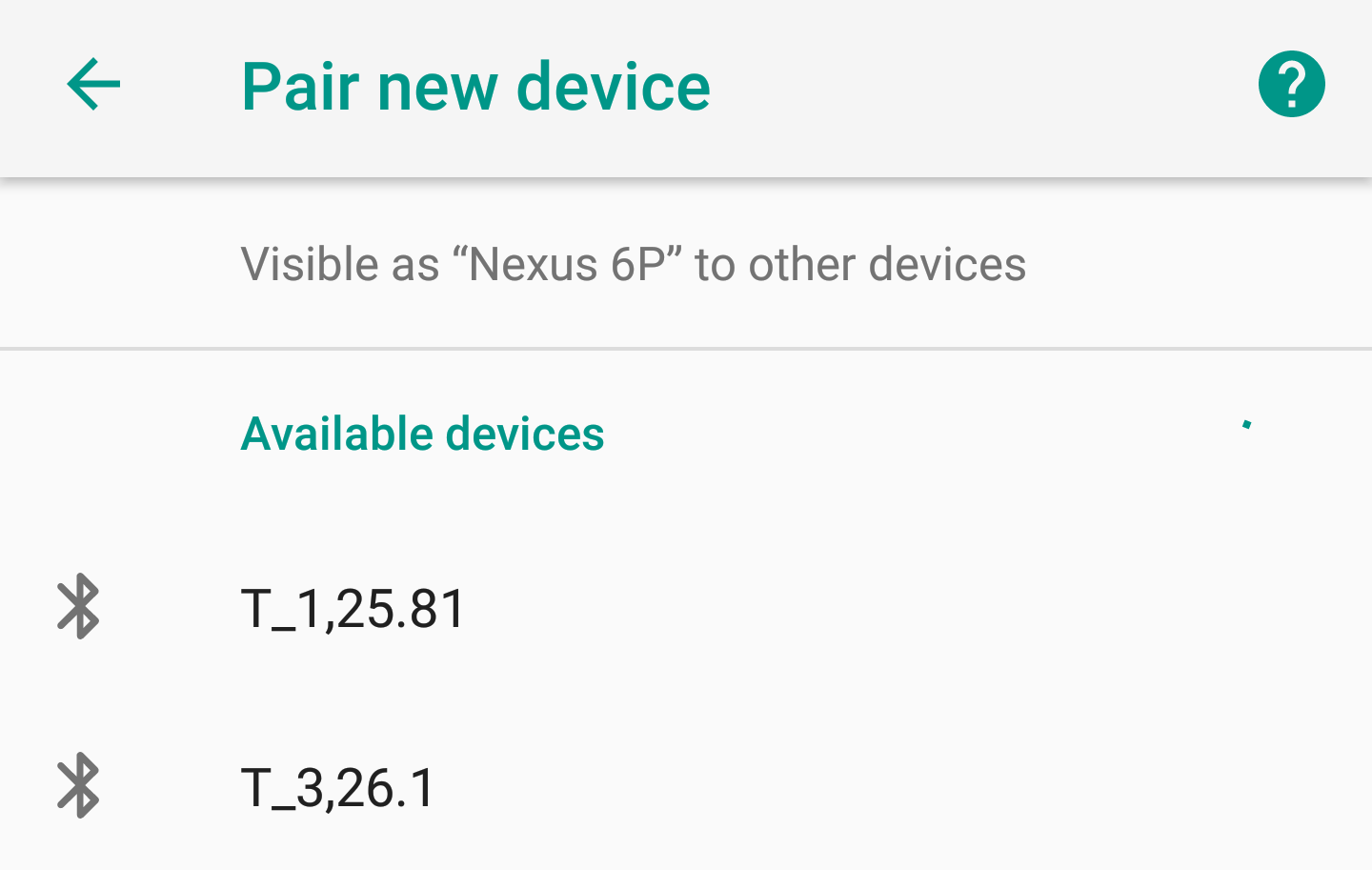
The temperature reading is broadcast, in plain text, as part of the device name by appending it, comma delimited, to the device name, e.g. T_1, 26.1 so you can just use your mobile's Bluetooth settings to scan for new devices in order to read the temperature. No special app is needed. Construction and programming of a BLE to WiFi bridge is also covered to allow you to feed the temperature readings into your WiFi network for data collection or control. Other very low power sensors can be easily added to the broadcast, such as relative humidity, barometric pressure and light levels by appending theses measurements to the name. Using just the device name to send the name/data allows for up to 26 bytes in total, after allowing for 3 bytes of flags (not connectable flag etc)
A number of different versions using different nRF52832 BLE modules are covered below. One of these modules is used in the revised BLE Room Temperature controlled Heater and as part of the Outdoor/Indoor weather station (under construction)
Part 3 of Easy Very Low Power BLE in Arduino – 2022 is an An Indoor / Outdoor Weather Station that extends this very low power temperature sensor to add a sensor for temperature, relative humidity and barometric pressure and display the values on a Weather Station. The sensors run for ~4 ½ years
Component
Selection and Construction
Total
Supply Current and Battery Life
Sensor
Code
Naming
Sensors
Temperature
Calibration
Single
Point Calibration
Multi-point
Calibration
Measurement Smoothing
BLE
to WiFi Bridge
Programming
the Adafruit Feather nRF52832
Programming
the HUZZAH ESP8266
Web
Page Temperature Display
pfodDevice
and Temperature plots
There are only two components:- A nRF52832 'bare' module and a coin cell (in a holder).
The following nRF52832 'bare' modules available from
Aliexpress can be used. They include:-
GT832E_01 ~US$15.90 mounts
on vero board
Jessinie XL52832-D01 nRF52832 module ~US4.90 and
Jessinie Test Board Adapter Plate for NRF52832 ~US$1.70 – Total
~US$5.60
BLM-KTB522 ~US$6.30 (no crystal) pin for pin replacement
for Skylab SKB369, needs to be mounted on PCB
Those 'bare' nRF52832 do not have any extra components or power regulators that will used extra current.
Add to this a CR2032 coin cell and holder,
e.g.
Sparkfun
coin cell holder PRT-00783 US$1.60 and CR2032
coin cell PRT-00338 ~US$2.10 – Total US$3.70
So using the Jessinie module and adapter and a coin cell and holder the total cost (excluding shipping) is < US$10
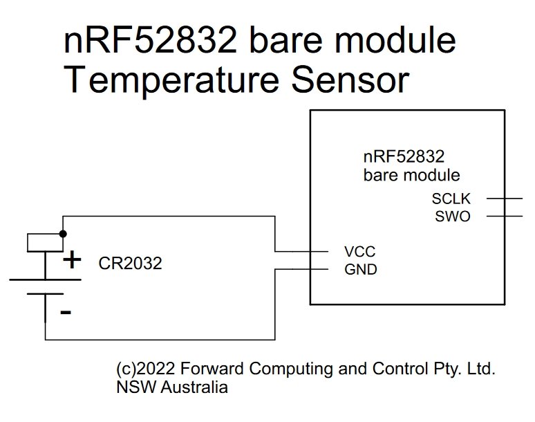
The schematic is trivial. Coin cell +ve goes to VCC and coin cell -ve goes to GND on the nRF52832 module. The SCK / SWD connections are used for programming.
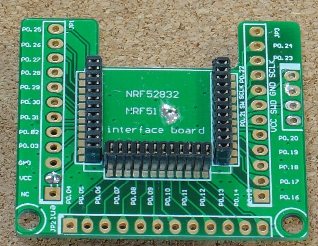
For the Jessinie module and adapter board the coin cell is mounted on the back of the adapter board.
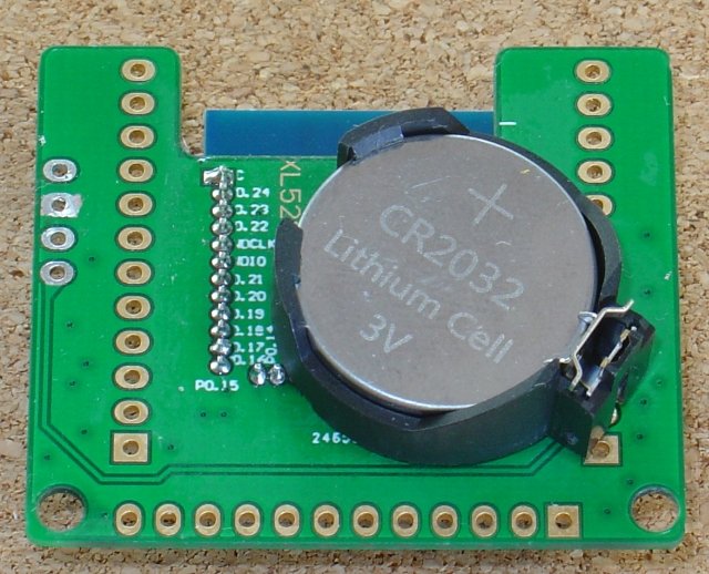
Drill a small hole (1mm) in the adapter board to accept the -ve pin of the coin cell holder when the +ve pin is in the VCC hole on the edge connector. See the photo below. The +ve coin cell pin is soldered into the VCC hole, the bottom left in the first photo, and the 1mm hole has been drilled in the earth plane and the green lacer scratched away to solder the coin cell holder's -ve pin.
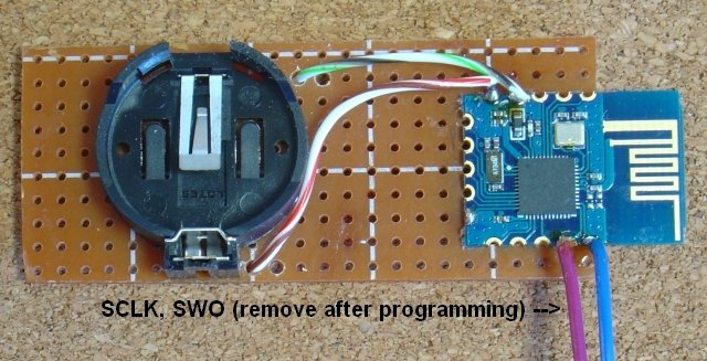
For the GT832E_01 as small piece of veroboard is used to mount the coin cell and the module
Wires from the bottom of the veroboard to the GT832E_01 edge contacts for VCC / GND and SCK / SWD (used for programming) hold the BLE module in place.
The BLM-KTB522 module needs PCB to mount it. Since it is a pin for pin replacement for the Skylab SKB369 module the PCB from the Easy Very Low Power BLE (2019) in Arduino Part 3 - Nano V2 Replacement can be used, but omitting all the additional components and voltage regulator and dual diodes with wire links to connect the coin cell directly to the BLM-KTB522 module.
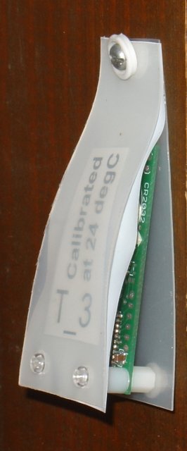
Having assembled the two components, you may want to add some dust protection as shown here, allowing free air flow around the nRF52832 chip. In this case the temperature monitor was screwed to the side if a book case to monitor the room temperature.
For leaving around the desk a sturdier mounting can be used using two small panels of 3mm perspex as show here.
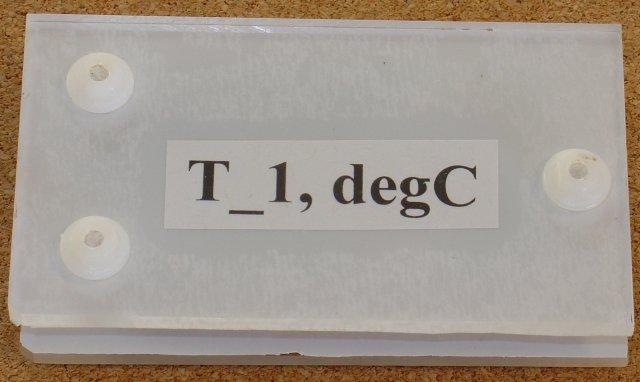
Again all sides are open to allow free air
flow around the nRF52832 chip and an opaque book covering plastic is
used to cut down heat pickup from sunlight. A top layer of reflective
foil was added as well.
nRF52832 modules with a 32Khz Crystal LowFreq clock, like GT832E_01 and Jessinie XL52832-D01 draws ~2.66uA when not advertising and ~28uA when advertising with a 750ms interval at +4 power
nRF52832 modules using an RC oscillator instead of a 32Khz crystal, like BLM-KTB522, draws ~4.4uA when not advertising, i.e. ~2uA more due to turning on the high frequency clock every 8secs or so to re-calibrate the low frequency RC oscillator. Advertising again draws ~28uA
So with BLE_ADVERT_MS set to 10*1000 (ms) and BLE_NO_ADVERT_MS set to 90*1000 (ms) in the lp_BLE_Temp_uC.ino sketch, i.e. for 10sec of advertising in every 100sec, gives the following average currents.
For nRF52832 modules
which have 32Khz Crystal LowFreq clock: 10sec advert in 100sec =>
28uA*10/100 + 2.66uA*(100-10)/100 = ~5.2uA
For nRF52832 modules
using a RC LowFreq clock: 10sec advert in 100sec => 28uA*10/100 +
4.4uA*(100-10)/100 = ~6.76uA
CR2032 coin
cells have ~235mAh when discharged down to 2V
https://data.energizer.com/pdfs/cr2032_eu.pdf,
which equates to
for nRF52832 modules which have 32Khz Crystal
LowFreq clock: 235e-3Ahr/5.2e-6A = 45192hrs => 1883 days =>
~5years 2months (e.g. GT832E_01/Jessinie XL52832-D01 modules) and
for
nRF52832 modules using a RC LowFreq clock: 235e-3Ahr/6.76e-6uA =
34763hrs => 1448 days => ~4years (eg KTBM522 module)
Follow the instructions in Easy Very Low Power BLE in Arduino -- Part 1 2022 to setup the Very Low Power BLE support for nRF52832 boards and programmers.
Then program the nRF52832 board with the lp_BLE_Temp_uC.ino sketch. This sketch advertises the uC temperature for 10secs in every 30secs. Once you have calibrated your uC, then edit the BLE_ADVERT_MS and BLE_NO_ADVERT_MS times to only advertise for 10sec in every 100secs to get the 5year batter life. See the comments in the sketch.
Since these sensors are so simple and inexpansive to make, you may well end up with a number of them advertising the temperature and/or other measurements, from various locations. To distinguish between them, the lp_BLE_Temp_uC.ino sketch uses the following convention. The temperature sensors advertised name starts with T_ followed by a number, e.g T_1, followed by a comma and the temperature value. This design will also be the basis for other sensors which add a very low power, temperature/humdity sensor or a temperature/humdity/barometric pressure sensor and/or a lux sensor.
This project used the following name format
Format of advertised name, e.g.
T_5,25.5
LOCAL_NAME prefix T_.. devices LOCAL_NAME,degC
LOCAL_NAME
prefix H_.. devices LOCAL_NAME,degC,%RH
LOCAL_NAME
prefix W_.. devices LOCAL_NAME,degC,%RH,hPa
LOCAL_NAME
prefix WL_.. devices LOCAL_NAME,degC,%RH,hPa,Lux
Set LOCAL_NAME, at the top of the lp_BLE_Temp_uC.ino sketch and then use the prefix to parse the advertised data. See the example code below.
Depending on the application, there are two calibration methods. For a temperature monitor, which is used to control room heating/cooling for example, as single point calibration is all that is needed. For a temperature sensor, which will be used in a weather station, a more extensive calculation over a wider temperature range is needed.
For a temperature monitor that is used to turn room heating/cooling on/off, the nRF52832 uC temperature sensor only needs to be calibrated at a single temperature, near the nominal desired room temperature, say 25degC.
Insert the coin cell, let the temperature monitor stabilize. You will find the uC temperature is sensitive to you touching it while inserting the coin cell. Scan for the monitor and read off the temperature and compare it to another temperature device, thermometer etc. This will give you the temperature error for the uC at that temperature. Then edit the lp_BLE_Temp_uC.ino sketch to add this correction to the uC reading to get the actual temperature.
float T_offset = 0; // to be set in calibration
float tempCompensation(float reading) {
  return reading+T_offset;
}
If you want the reading in Fahrenheit instead of Centigrade, you can include that adjustment in the tempCompensation() method.
float T_offset = 0; // to be set in calibration
float tempCompensation(float reading) {
  reading = reading * 1.8 + 32;   // convert to Fahrenheit
  reading = reading+T_offset; // adjust for error in Fahrenheit.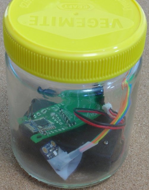
}For an environmental temperature sensor, the uC temperature sensor need to be calibrated over a range of values. A water bath can be used calibrating temperatures in the range 5C to 90C
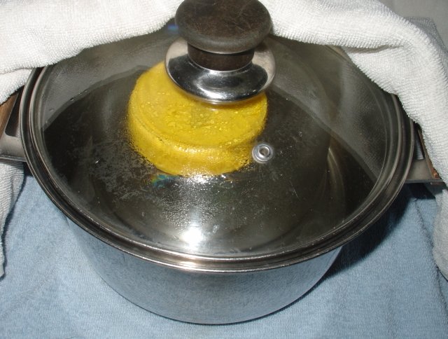
Where the sensor is placed in the water proof
jar in the water. For low temperatures, it is placed in the freezer
to freeze the water. For high temperatures, near boiling water is
used. In both cases the bath is wrapped in towels and or bubble wrap
to slow down the temperature change so that the uC has time to
stabilize at each temperature measured.
For this calibration it is convenient to add a more accurate temperature sensor to the circuit and to advertise both readings.
Here a KTMB522 (a SKB369 pin for pin replacement) is being calibrated using a Si7021 and a PCB from Easy Very Low Power BLE in Arduino (2019) Part 3 - Nano V2 Replacement. On that PCB SDA is connected to P0.28 and SCL connected to P0.31 which are different from the programmed default of SDA - P0.09 and SCL – P0.10, so Wire.setPins(28,31); is called before calling Wire.begin(); to set SDA as P0.28 and SCL as P0.31.

The
KTMB522 does not have low frequency 32Khz crystal, so you need to
program it using the Generic
nRF52832 (LFC RC osc) board
setting.
The KTMB522 / Si7021 is programmed with the lp_BLE_TempCalibration.ino sketch. Unzip lp_BLE_TempCalibration.zip to your Arduino sketch directory. That sketch that advertises as T_0, followed by the Si7021 temperature reading, followed by the error between the KTMB522 uC temperature reading and the Si7021 (i.e. KTMB522 – Si7021), comma separated. The sketch advertises this data for 10secs in each 30secs.
To record the data you can use an Adafruit nRF52832 Feather board programmed with the bleTempCalibrationScanner.ino sketch. That sketch continually scans for a device starting with T_0, and just prints the broadcast name to Serial. Once the scan finds a T_0, device it skips reporting it for the next 11secs so that only one new temperature reading is output each 30sec cycle. The output is logged by TeraTerm (or CoolTerm for Mac) to a log file for later analysis in OpenOffice Calc.

Above is
sample output for one module. The compensation equation is 3.75
degC if the
temperature reading is <21, otherwise (reading
– 30)*-0.145 + 2.44.
Approximate
error of +/-0.6 degC between 5C and 45C.
float tempCompensation(float reading) {
  //=if(reading<21);3.75;(reading-30)*-0.145+2.44)
  if (reading < 21) {
    reading += 3.75;
  } else {
    reading += (reading - 30) * (-0.145) + 2.44;
  }
  return reading; // deg C
}
This compensation process takes time, so you may prefer to just add a temperature sensor to the nRF52832 instead. The SparkFun BME280 module is a very low power temperature, relative humidity, barometric pressure sensor. The Adafruit Si7021 and BME280 breakout boards are not suitable as Adafruit has added extra current consuming components. Handy in other situations but not for very low power devices. The SparkFun BME280 board has minimal extra components which can be cut out of the circuit if necessary by cutting onboard links. The BME280 sensor itself is very low power. The data sheet lists 0.16uA average supply current for weather readings once a minute. The SparkFun BME280 is used, later, in a very low power BLE weather station project (under construction)
The output from the uC temperature sensor comes in discrete steps. For control, you can just use the measurement directly and if the device being controlled needs some temperature hysteresis or dwell on/off time (the time the device being controlled must remain on/off once it is switched on/off) then that can be added to the raw temperature.
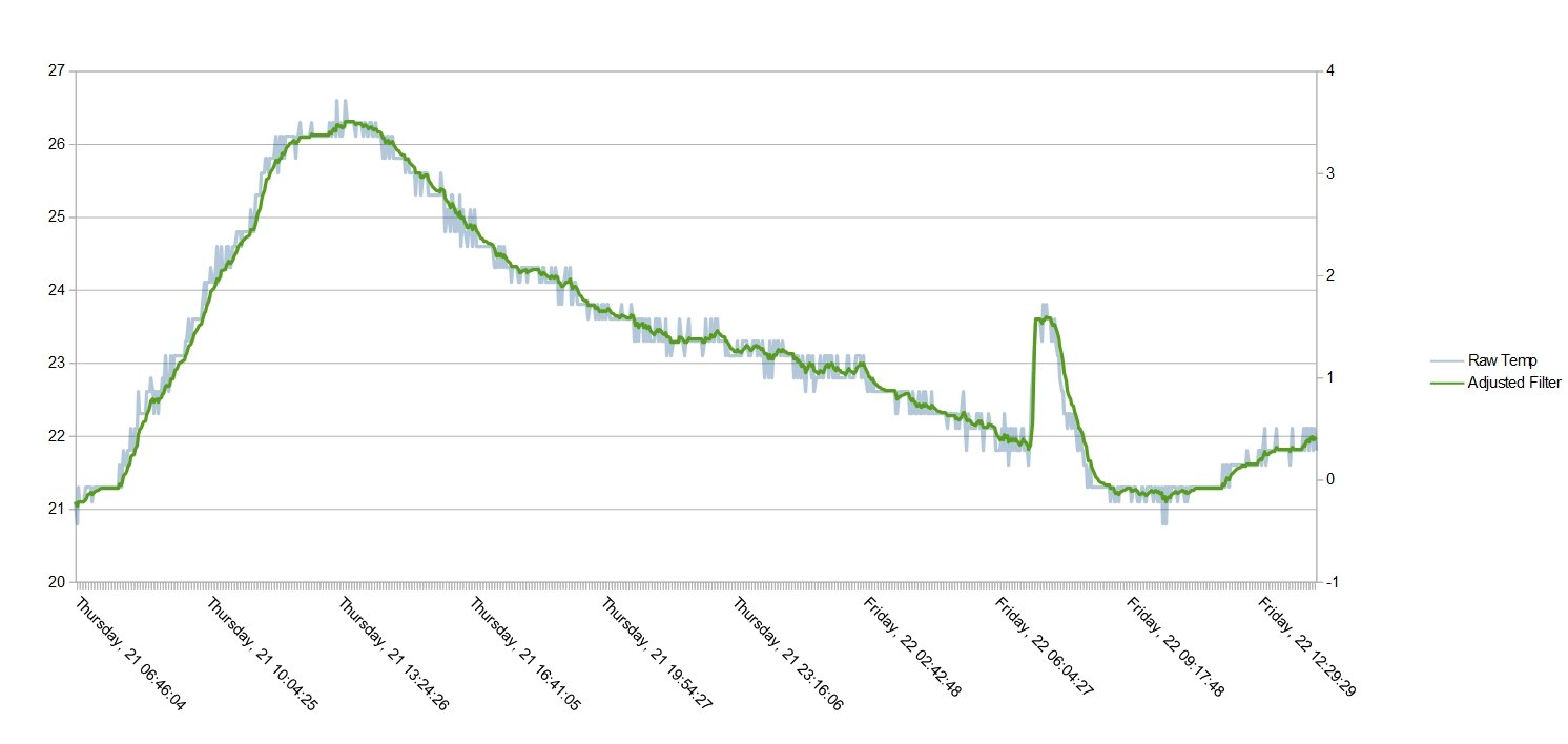
However for display purposes it is more pleasing to the eye to apply some filtering to these discrete measurements. The filter below an exponential filter with factor 0.2 and a step adjustment when the exponential filtered error exceeds 0.9 e.g.
float lastFilterValue = 0;
float exponentialFactor = 0.2;
float maxAbsError = 0.9;

float filterRawTemp(float rawTemp) {
  float filterResult =  exponentialFactor * rawTemp + (1 - exponentialFactor) * lastFilterValue;
  float filterError = rawTemp - filterResult;
  float absError = ((filterError) > 0 ? (filterError) : -(filterError));
  if (absError >  maxAbsError) {  // step to current value
    filterResult = rawTemp;
  }
  lastFilterValue = filterResult;
  return filterResult;
}
This gives the filtered output below, which still has some ripples but follows the rawTemp measurements closely and removes the spikes.
This BLE temperature sensor has limited range. BLE Mesh can be used to extend the range and integrate the measurement into a control/monitoring system. However BLE Meshes require non-trivial setup and programming and at the end of that the measurement is still limited to the local BLE Mesh. A simpler alternative is to use a BLE to WiFi Bridge to collect the data, from all devices within range, and make the measurement available via a webpage/data server or push the measurements out to the cloud for control or monitoring.
The project Simple WiFi to Bluetooth Low Energy (BLE) Bridge covers the hardware construction. The circuit is trivial.
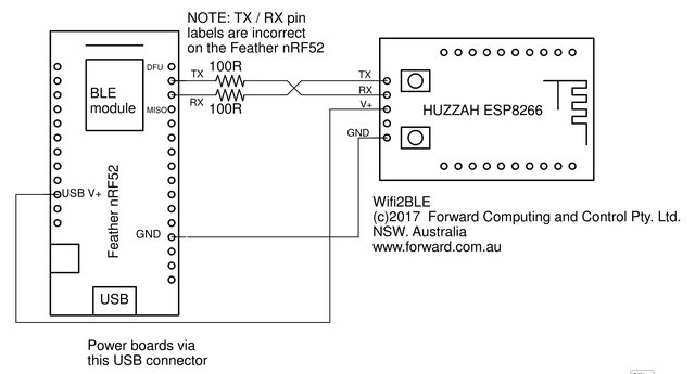
The Wifi2BLE circuit is shown above. A pdf version is here. As you can see the circuit is very simple. Just 4 wires and two 100 ohm protection resistors. The protection resistors are in case you miss-connect the TX / RX lines after programming the HUZZAH ESP8266 or the Feather nRF52.
NOTE: The Feather nRF52 board marking for the TX and RX pins are in-correct. The TX pin is actually the one next to the DFU pin and the RX pin is the one next to the MISO pin.
Make sure you connect the TX/RX lines as shown above. Fortunately the protection resistors did their job and boards were not damaged while I sorted out why the boards were not taking to each other.
To program the Adafruit Feather nRF52832, follow the instructions on downloading and installing the Arduino Board support for the Feather nRF52. Check you can connect to, and program the board via the USB cable.
The BLE sketch for the Adafruit Feather nRF52832 is in BLE2WiFi_bleScanner.zip sketch. Unzip it to your Arduino Sketch directory. You also need to install the SafeString library using the Arduino library manager.
Disconnect the ESP8266 Tx/Rx connections when programming the Adafruit Feather nRF52832 or the ESP
The BLE2WiFi_bleScanner.ino sketch simply continually scans for BLE devices and check if their advertised name starts with one of those we are interested in. A linked list is used to hold the names wer are interested in as well as when they were last scanned. Once a device of interest has been found, its advertised name is output to Serial and further scans of it are ignored for the next 11secs. The code looks for devices T0, and T1, you can added more if you wish.
To program the shield follow the instructions given on https://github.com/esp8266/Arduino under Installing With Boards Manager. When opening the Boards Manager from the Tools → Board menu and select Type Contributed and install the esp8266 platform. This project was compiled using the ESP8266 version 2.3.0. Other versions will have their own set of bugs and may not work with this code.
NOTE: DO NOT use the Adafruit Board install as the sketch used here will not compile under that code.
Close and re-open the Arduino IDE and you can
now select “Adafruit HUZZAH ESP8266” from the Tools →
Board menu. (see the Simple
WiFi to Bluetooth Low Energy (BLE) Bridge )
Other ESP8266 or
ESP32 modules can also be used for the WiFi module. For ESP32 modules
follow the instructions given on
https://github.com/espressif/arduino-esp32
under Installing (Windows, Linux and macOS)
There are lots of ways you could use the ESP to
make your temperature measurements available over WiFi, for example
using MQTT, here two simple examples are provided :-
1) The first
one just makes the latest measurement available on a webpage.
2)
The second uses pfodApp
on an Android mobile to display the latest measurement and a plot of
the last 24hrs temperatures with day and time. No Android programming
is required and the plot data can be save to a file for further
processing. The free pfodDesigner
app generates the pfodApp server/menu/plot code for you.
The example is based on the ESP8266 example code from ESP32 / ESP8266 Auto WiFi Config and displays just a simple text web page. It is left as an exercise to the reader to create a 'pretty' webpage display.
The example web page sketch is in BLE2WiFi_ESP8266Web_example.zip Unzip it to your Arduino Sketch directory.
Download this library zip file, ESPAutoWiFiConfig.zip, and install it using the Sketch → Include Library → Add .ZIP File menu in the Arduino IDE . You also need to install the SafeString library V4.1.19+ from the Arduino library manager.
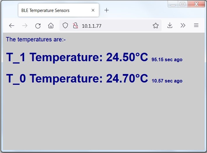
This sketch, BLE2WiFi_ESP8266Web_example.ino, first tries to
connect to a local router. If it cannot it starts its own access
point called WiFiConfig with a password of 12345678 and
serves a network configuration webpage at 192.168.1.1 for you to set
your network's SSID and password and also set the static IP
(10.1.1.77 in the example above) that you will connect to to display
the temperatures.
See ESP32
/ ESP8266 Auto WiFi Config for more details
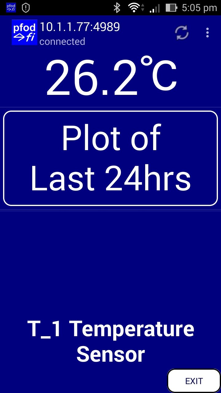
The second example sets up the ESP8266 as a pfodDevice, which pfodApp V3.0.394+ can connect to display the data served.
The advantage of pfodApp is the simplicity of coding to obtain a plot of the temperature sensor against day and time on your Android mobile. The free pfodDesignerV3 Android app generates the menu and plot messages that you design and all that remains is to parse the incoming data and save it to send out, in CSV format, for plotting by pfodApp. Arduino Date and Time using millis() and pfodApp covers creating plots with pfodDesignerV3, while How to Display/Plot Arduino Data on Android shows how to add a Chart button to a pfodMenu using pfodDesignerV3
The sketch BLE2WiFi_ESP8266_pfod_plot.ino accumulates the data from T_1 sent to the ESP8266 over the Serial connection and ignores any other devices' data. That sketch also contains the pfodApp menu from the pfodDesignerV3 that opens a plot screen on the Android mobile. When you click on the “Plot of Last 24hrs” button, the pfodApp opens a plot screen and th sketch then sends the accumulated data in CSV format and the pfodApp plots it against day and time.
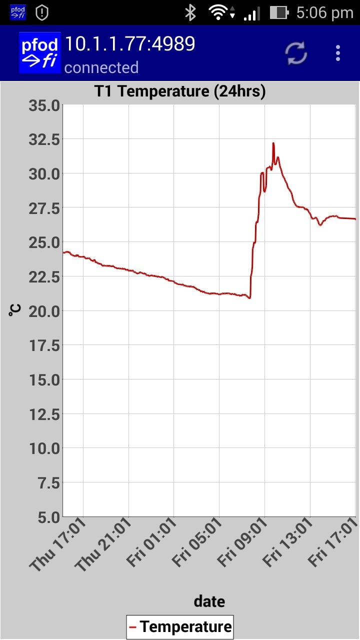
The pfodApp does all the work. The command to open the plot is
{=T1 Temperature (24hrs)`870~E
HH:mm~C|date|Temperature~35~5~\342\204\203||}
The 870 is the
maximum number of points to plot. The E HH:mm is the format for
showing the x-axis in day and time hr:mm. The C means clear out any
previous plot data.
Then follows the CSV fields date, temperature
from 35 to 5 labled as degC (\342\204\203 is
octal for the degC unicode symbol) and then two more data fields
which are ignored for this plot.
If the data exceeds the 5 to 35 degC range the plot auto scales. You can also use two fingers to zoom the plot in and out in both directions.
This tutorial has presented a very simple, very low power BLE temperature sensor using only two components, a nRF52832 'bare' module and a coin cell. Average supply current is ~6uA which equates to ~5years life from a CR2032 coin cell.
The onboard uC temperature sensor is not very accurate, but a single point calibration is all that is needed for a room temperature monitor to control heating/cooling. Mult-point calibration can be used to obtain ~+/-0.6C accuracy over a 5C to 45C. One of these modules is used in the revised BLE Room Temperature controlled Heater to remotely sense the room temperature.
The measured temperature is broadcasts as part of the modules advertised name, and so can be read by a mobile by just scanning for near by devices. The construction and programming of a BLE to WiFi bridge was also described so that the sensed temperature can be feed into an area control/monitoring system or monitored remotely.
AndroidTM is a trademark of Google Inc. For use of the Arduino name see http://arduino.cc/en/Main/FAQ
The General Purpose Android/Arduino Control App.
pfodDevice™ and pfodApp™ are trade marks of Forward Computing and Control Pty. Ltd.

Contact Forward Computing and Control by
©Copyright 1996-2020 Forward Computing and Control Pty. Ltd.
ACN 003 669 994