
|
Home
| pfodApps/pfodDevices
| WebStringTemplates
| Java/J2EE
| Unix
| Torches
| Superannuation
| CRPS Treatment
|
| About
Us
|
|
|
ESP32 / ESP8266 Auto WiFi Config |
by Matthew Ford 6th February 2025
(originally posted 7th April 2022)
© Forward
Computing and Control Pty. Ltd. NSW Australia
All rights reserved.
Update 6th Febrary 2025: Added a optional
deviceName
Update 17th August 2022: Added a little
padding to front of EEPROM storage
Update 26th July
2022: ESPAutoWiFiConfig now available from Arduino
Library manager
Update 15th May 2022: Rev 2.1
added reboot on loss of connection, clearRebootFlag while try trying
to connect, added defaultNetworkSettings (see below)
Update 30th
April 2022: Rev 2 supports ESP32-C3, ESP32-S2, ESP32-S3, etc that
have a ws2312 RGB addressable led
This simple code allows you to easily connect your ESP32 or ESP8266 device to any network without recoding. It avoids hard coded network SSID, password and IP settings and provides a simple webpage to complete the setup. Just turn the device on and when the led to start flashing rapidly, scan the QR code to connect to the device and open the http://192.168.1.1 web page to complete the network setup. This code also takes care of connecting to the local network connection with just two simple method calls, once you have set the WiFi settings.
The 3D Printed Personalised Word Clock by TechKiwiGadgets uses ESPAutoWiFiConfig so users can easily setup their clock to connect to their WiFi network.

You need a led to indicate when the WiFi configuration is active. This can be a on-board lead or a led connected to a pin of your choice.
The code you need to add to your project is trivial. Use open menu Sketch → Include Library → Manage Libraries... and search for ESPAutoWiFiConfig and install. If prompted to install the SafeString library say yes as it is also needed.
For manual install, download this library zip file, ESPAutoWiFiConfig.zip, and install it using the Sketch → Include Library → Add .ZIP File menu in the Arduino IDE . You also need to install the SafeString library V4.1.19+ from the Arduino library manager.
Then add this code to your startup() and loop() methods.
#include "ESPAutoWiFiConfig.h"

void setup() {
  // setup code that must be run every time
  // ..

  // check if we should start access point to configure WiFi settings
  if (ESPAutoWiFiConfigSetup(ledPin, highForLedOn, eepromOffset)) {
    return; // in config mode so skip rest of setup
  }

  // when we get here the WiFi has connected !!

  // normal setup code that is run when not configuring the WiFi settings
  // ...
}

void loop() {
  //  .. other code that MUST run all the time

  if (ESPAutoWiFiConfigLoop()) {  // handle WiFi config webpages
    return;  // skip the rest of the loop until config finished
  }

  // .. normal loop code here that is run when not configuring the WiFi settings
}
The ledPin specifies which pin drives the indicator led and highForLedOn is either true or false. true if a high output turns the led on, false if a low output turns the led on. The eepromOffset is 0 unless you are using EEPROM in your own code, in which case it is the size of your EEPROM.begin( ) so that the WiFi configuration data is written after your data.
By default when the WiFi has connected the led is turned OFF when highForLedOn is set correctly. If you want to keep the led ON when the WiFi is connected just invert the value of highForLedOn.
As of V2.2.2 you can also optionally add a
deviceName that will be shown on the configuration web page to
identify which device you are configuring.
e.g.
const char deviceName[] = "Name of your device"; // optional, only first 50 char are used

void setup() {
  // setup code that must be run every time
  // ..

  // check if we should start access point to configure WiFi settings
  if (ESPAutoWiFiConfigSetup(ledPin, highForLedOn, eepromOffset, deviceName)) {
    return; // in config mode so skip rest of setup
  }

  // when we get here the WiFi has connected !!

  // normal setup code that is run when not configuring the WiFi settings
  // ...
}
For boards that have a ws2812 RGB led fitted, e.g. ESP32-C3, ESP32-S2 and ESP32-S3, you pass in minus of the ledPin that drives the RGB led. The -ve ledPin indicates to ESPAutoWiFiConfig that it should use the ws2812 driver for that pin. For ESP32 boards with ws2812 leds, you can also use ESPAutoWiFiConfig_setColor(uint8_t _red, uint8_t _green, uint8_t _blue); method to set the led color
Example
settings are:-
For
ESP8266,
ESP-01, ESP-01S use:-
bool
highForLedOn = false; //
need to make output low to turn Adafruit ESP8266 HUZZAH's and ESP-01s
and ESP-01 Led ON, turns led OFF when WiFi connected.
and
int
ledPin = 0; for
Adafruit ESP8266 HUZZAH - onboard Led connected to GPIO0
int
ledPin = 2; for
ESP-01S (Blue led on GPIO2)
int
ledPin = 1; for
ESP-01 (Blue led on TX (GPIO1), ESP-01 also has a Red power led)
For
ESP32
,
e.g. SparkFun ESP32 Thing, use:-
bool
highForLedOn = true; //
need to make output high to turn Sparkfun ESP32 Thing Led ON, turns
led OFF when WiFi connected.
int
ledPin = 5; //
for Sparkfun ESP32 Thing - onboard Led connected to GPIO5
For
ESP32
C3/S2/S3 which
have a ws2812 addressable RGB led fitted use:-
bool
highForLedOn = true; //
turns led OFF when WiFi connected
and, -ve indicates the ws2812
driver is to be used
int
pinNo = -2; //
for Adafruit ESP32C3 QTPY neopixel led
int
pinNo = -8; //
for ESP32-C3 ws2818 pin
int
pinNo = -18; //for
ESP32-S2-DevKitM-1 ws2818 pin
int
pinNo = -18; //
for ESP32-S2-Saola-1 ws2818 pin
int
pinNo = -48; //
for ESP32-S3-DevKitC-1 ws2818 pin
For complete examples see the examples directory of the ESPAutoWiFiConfig library, ESP8266ConfigExample.ino, ESP32ConfigExample.ino and ESP32C3_ConfigExample.ino. Those sketches implement a simple hello server which you can access via the static IP you set as part of the WiFi auto config. The same ESPAutoWiFiConfig files are used for both the ESP32 and ESP8266. This software has been tested with Arduino IDE 1.8.19 and ESP32 board support V2.0.2 and ESP8266 board support V3.0.2
If your boards completely clears the flash memory when programming you will loose any WiFi settings you have previously configured. To avoid having to continually reset the WiFi settings you can modify the ESPAutoWiFiConfig.cpp file to add your test network details to the defaultNetworkSettings() method near the top of the file. If defaultNetworkSettings() returns true the current settings in the storage object will be used. See the ESPAutoWiFiConfig.cpp code for an example. Of course when you release your code, just point the user here to download the library without any default network settings.
Here are the instructions for the user to configure their WiFi settings.
1) Turn the device. The led will flash slowly for 30secs while the device tries to connect to the last configured settings.
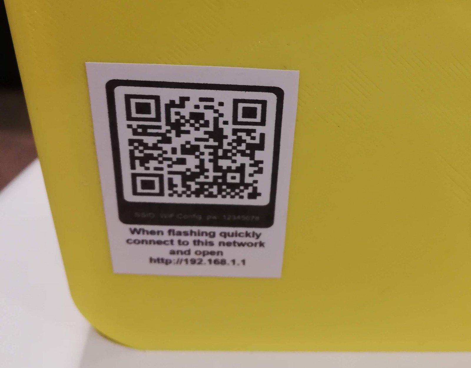
2) Then the led will flash quickly, indicating
that the WiFi configuration mode is active. Scan the QR code
(attached to the device) to connect your phone to the device,
SSID:
WiFiConfig,
password: 12345678
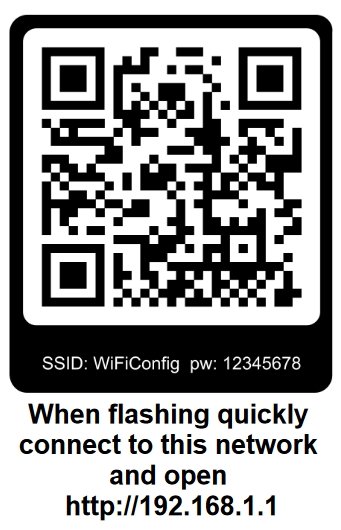
Then open a web browser and type in http://192.168.1.1. to display the WiFi configuration page. (This configuration page may also popup automagically.)
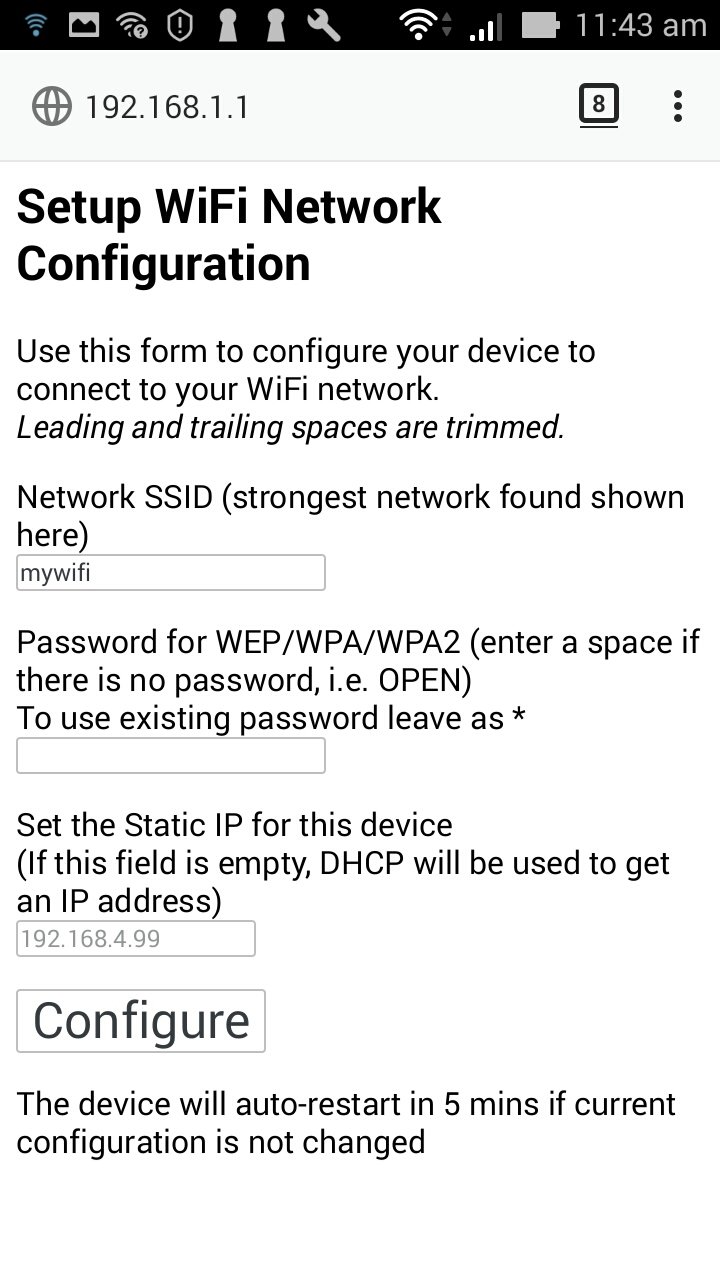
Fill in the settings for your WiFi and a static IP, if you need one, and click Configure. If your device is running as a server, then you probably want to specify a static IP so you know were to connect to it.
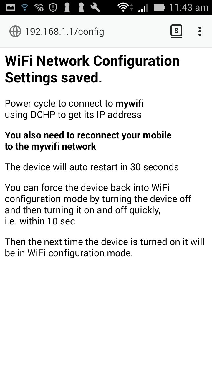
As noted on the saved page, you can force the device back into WiFi configuration mode, to change the static IP for example, by turning the device off and then turning it on and off quickly (within 10 seconds). Then the next time you turn the device on it will start in WiFi configuration mode.
There is no hard coded WiFi data for your network in the code.
The ESP
access point for configuration is hard coded as SSID: WiFiConfig
pw: 12345678
However the
ESP access point has very limited range and a so hacker would have to
be physically close and listening just as you press the Configure
button, since your network password is never sent back when the
config setup page is re-displayed.
If this possibility concerns you, you can set your own access point SSID and password. This QR code generator https://qr-code-generator.org seems to be a simple one uncluttered by adds. (see Creating the QR codes in the ESP-01 Timer Switch project.) However, presumably you would still attach the revised QR code, with these new details, to the device for ease of use and memory.
This tutorial has shown how easy it is to setup and edit the WiFi setting on your ESP devices with out having to re-program it. The extra code is trivial and the process for the user is not complicated. The two simple method calls also take care of connecting to your WiFi network once you configure the settings.
For use of the Arduino name see http://arduino.cc/en/Main/FAQ
The General Purpose Android/Arduino Control App.
pfodDevice™ and pfodApp™ are trade marks of Forward Computing and Control Pty. Ltd.

Contact Forward Computing and Control by
©Copyright 1996-2024 Forward Computing and Control Pty. Ltd.
ACN 003 669 994