
|
Home
| pfodApps/pfodDevices
| WebStringTemplates
| Java/J2EE
| Unix
| Torches
| Superannuation
|
| About
Us
|

|
Android Controlled C++ micro:bit
|
by Matthew Ford 5th June 2017 (original
5th July 2016)
© Forward Computing and Control
Pty. Ltd. NSW Australia
All rights reserved.


Update
15th
January
2017: Lancaster Uni is changing the micro:bit UART service (issue
#259).
pfodApp
supports both the old and new style services so this change will not
effect pfodApp users.
Update:
21st
December 2106 – Fixing paring
with Pixel
If you are having
problems paring with Pixel or other Android 7.1 mobiles, implement
the 500mS delay shown in this
GitHub pull request #225
This tutorial will cover
:-
Reading
an Input Voltage and Switching an Output
Plotting
and Logging the Measured Input Voltage
Displaying,
Plotting and Logging the Measured Temperature.
Also see Getting Started with micro:bit C++ which covers debugging, fibers and monitors and semaphores.
There are a number of programming tools for the BBC micro:bit, but the combination of pfodDesignerV2 and pfodApp lets you use your Android mobile to design a custom menu (and sub-menus) and create charts and log data. After designing your Android interface with the free pfodDesignerV2, you can preview the resulting menu exactly as it will be displayed by pfodApp, before generating the C++ files to load into your micro:bit, via the off-line Netbeans compiler. Then when you have set up a Bluetooth Low Energy (BLE) connection from pfodApp to your micro:bit, your menu will be displayed, letting you control your micro:bit's outputs and read, chart and log it inputs.
pfodDesigner provides a range of menu design options
that cover :-
Setting a Digital Output pin High or Low or
pulsing the pin High or Low for a set time interval.
Setting the
value of an Analog Output (PWM)
Displaying the state of a Digital
Input.
Displaying the value of an Analog Input
Charting and
Logging Analog Inputs.
Adding a general purpose Button, a Sub-Menu
or a Label.
In each case you have complete control over the text displayed for the High/Low inputs, the scaling and offset and units used for the Analog inputs and charts and logs as well as the font sizes, colours, format etc.
pfodDesignerV2 already supported a wide range of Arduino style boards connected via Bluetooth Classic, Bluetooth Low Energy, WiFi, Ethernet or SMS. pfodDesignerV2 V2.2211+ adds support for designing for the BBC micro:bit board. For the BBC micro:bit, the pfodDesignerV2 generates a single cpp class, pfodMenu which together with pfodParserMB library and Lancaster University microbit C++ support libraries compiles to serve your custom menu to pfodApp running on your Android mobile. There are a few steps involved in setting up to code the micro:bit using C++. The Offline Compiler Setup for BBC micro:bit page explains how to do that.
This first simple menu is going to read and display the voltage applied to one of the micro:bit's analog inputs and add a control to turn one of micro:bit's digital outputs on and off. Apart from the different pin names and capabilities of the BBC micro:bit board, the rest of the pfodDesignerV2 menus are unchanged from board to board so you can also work through the tutorials on the pfodDesignerV2 page. Just be sure the set the board to BBC micro:bit when starting each menu.
There are three parts to this first example:-
Design the menu using the free pfodDesignerV2 android app and generate the code.
Setup the Offline Netbeans C++ compiler for the BBC micro:bit and replace the pfodMenu.h and pfodMenu.cpp files with the generated code.
Install the pfodApp on your Android. Register your micro:bit with your Android and then set up a pfodApp connection to your micro:bit to display your menu showing the Input Voltage.
None of these steps involve writing any C++ or Android code.
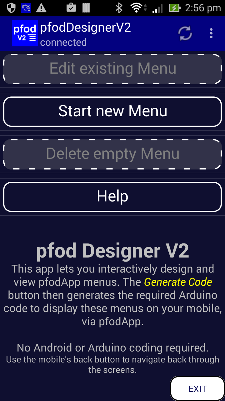
Install the free pfodDesignerV2 from the Google Play Store and click Start New Menu

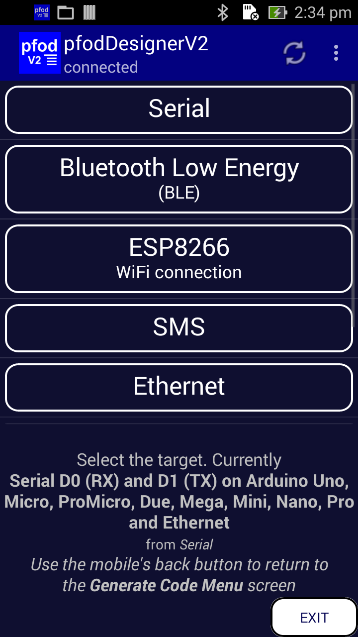
Then click Target button to change the target and choose Bluetooth Low Energy targets and select BBC micro:bit.

Use your mobile's back button to get back to the Editing Menu_1 screen.
Now click Add Menu Item. Scroll down and select Data Display. This opens the editing screen for that menu item. At the top of the screen is a preview (Reading 775) of the menu item as currently configured. The 775 reading is just a preview example value.

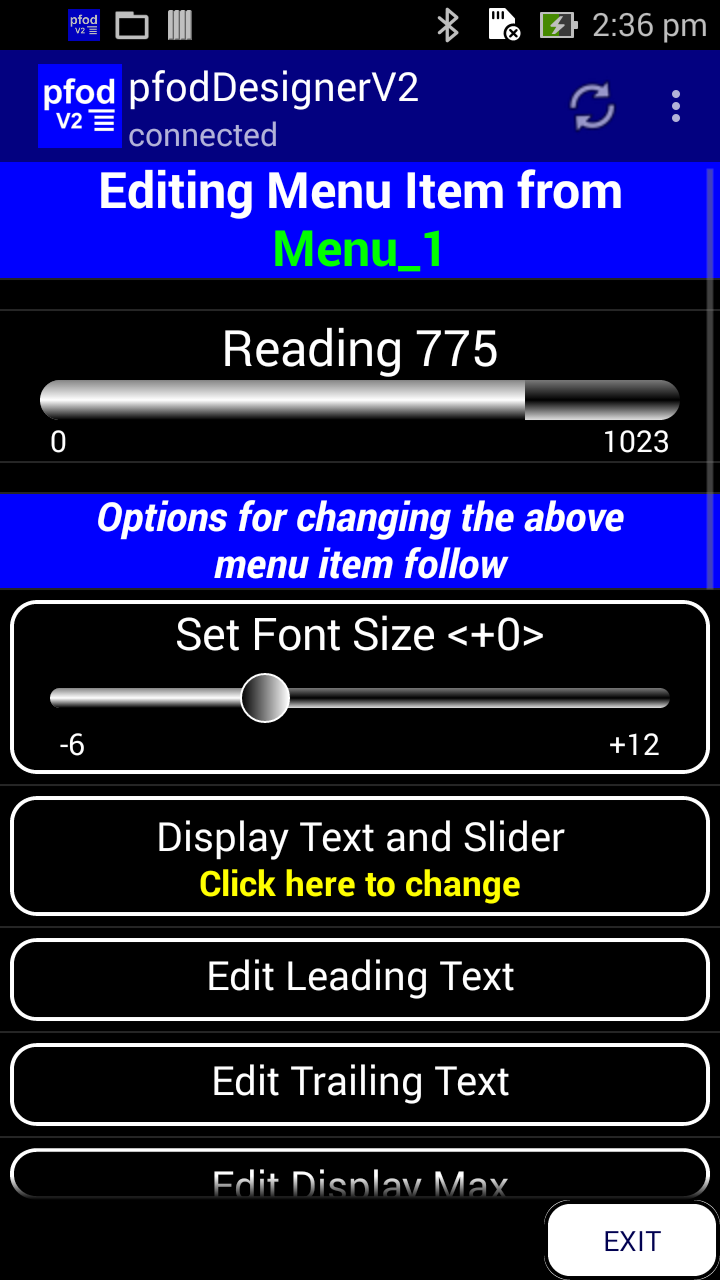
To connect this display to an input pin, scroll down and click Not connected to an I/O pin. This opens a list of micro:bits Analog capable pins that have not already been assigned to other menu items.

Choose P0 as
the input. When the code is generated, it will connect the menut
display to the analog value read from micro:bit's P0 pin.
Go back to the Editing Menu_1 screen and select Preview Menu to see what the final menu currently looks like.

There are two things about this menu that need to be improved:-
The Prompt needs to be changed
The display of the AtoD reading from P0 needs to be converted to a Volts value/display.
Go back to the Editing
Menu_1 screen and open the Edit
Prompt screen and edit the prompt to
something suitable (see the pfodDesignerV2
tutorials for detailed examples of editing the prompt). The
prompt background colour set the default colour for the whole menu,
but you can override it in each menu item with another background
colour.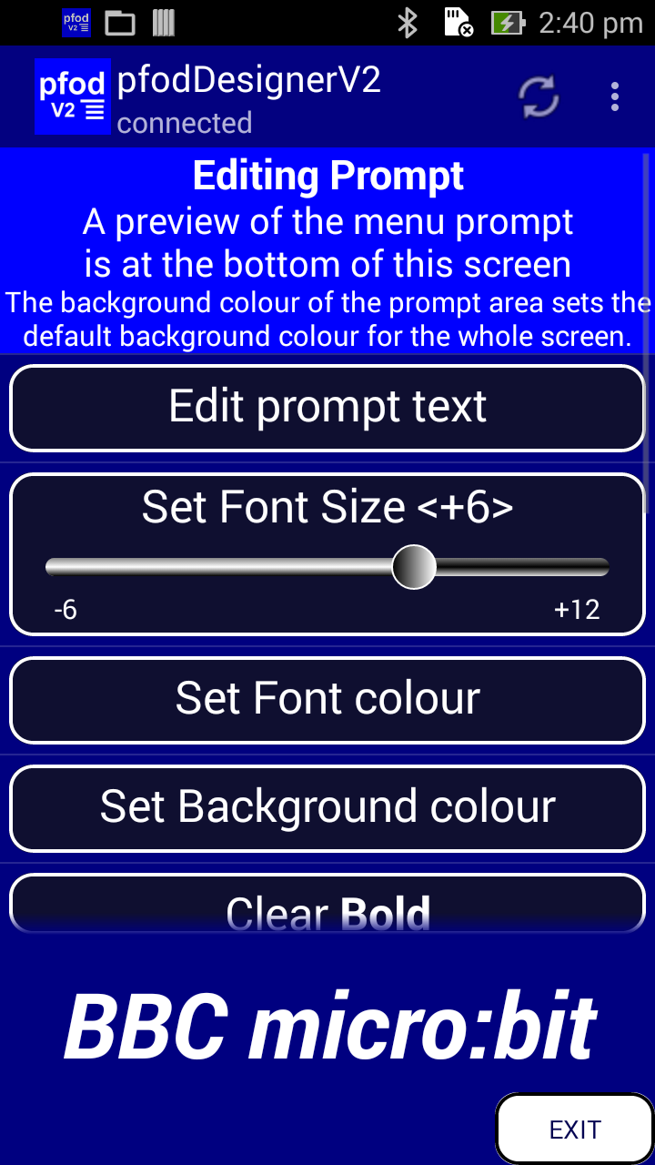
Having fixed the prompt, return the the Editing Menu_1 screen and select Edit Menu and click on Reading (Data Display) to open that menu item for editing.


Edit Leading
Text to “P0 “. Edit
Trailing Text to “V” You
can also edit the font size, colour style and background if you wish.
Here I have increased the font size.
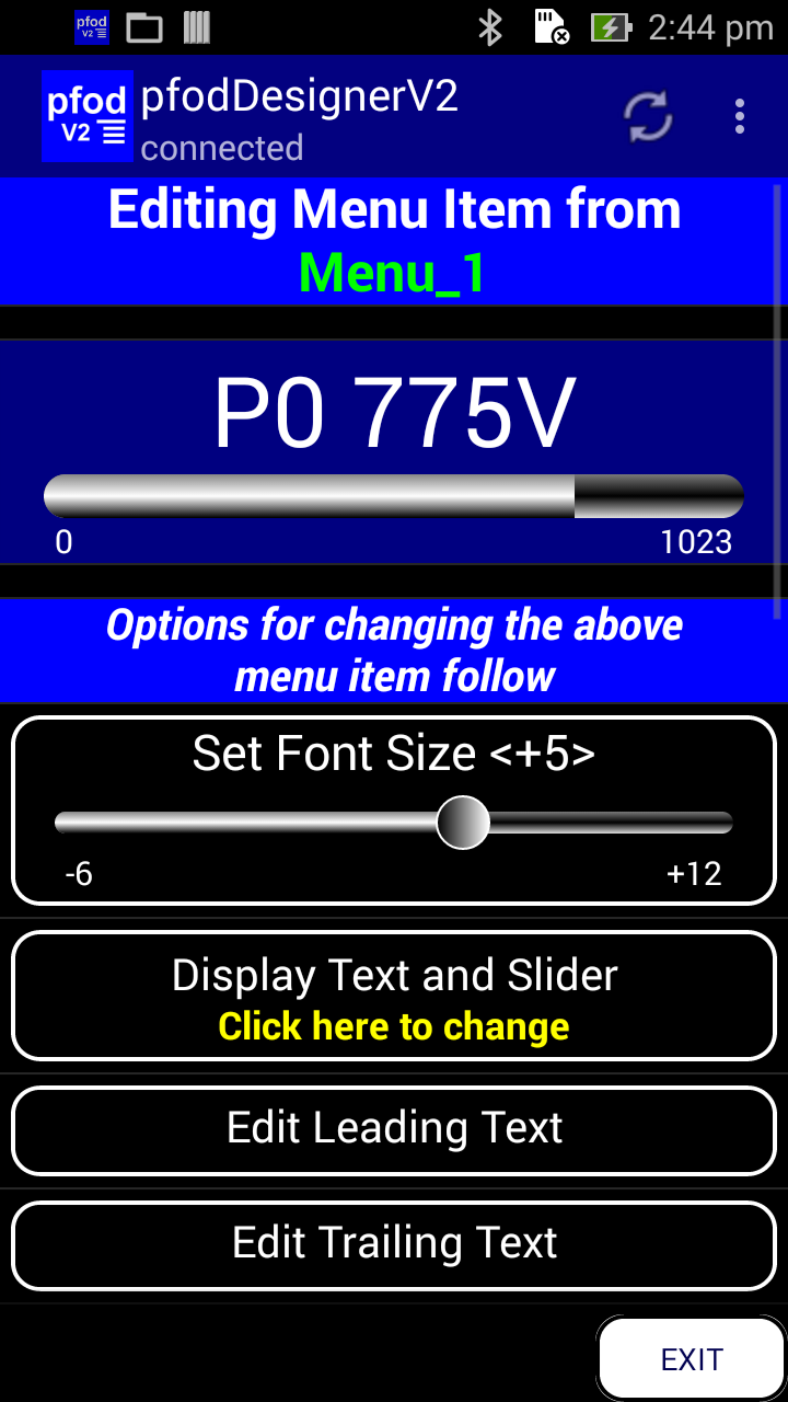
The sets the text. To set the scaling there are 4 values that can be changed.
You can Edit Data Variable Range to set the expected range of the raw measure value. These numbers are ALWAYS integers and for micro:bit Analog inputs the default range of 0 to 1023 is correct.
The other two values set the Display Max and Display Min. These values can be decimal values and set the scaling from the Data Variable Range to the slider display. In this case a raw measured value of 1023 == 3.3V and 0 == 0V so you only need to Edit the Display Max to “3.3”. Then go back Editing Menu_1 and preview your current design. Note that the 775 example reading has now been scaled to 0 to 1023 counts == 0V to 3.3V


The pfodApp menus on your mobile are only updated when pfodApp requests them. To have the menu update with the latest reading from P0 you should set a menu refresh interval. Go back to the Editing Menu_1 screen and set the Refresh Interval to 1 sec.

In Editing Menu_1 screen and click on Add Menu Item and select On/Off Setting or Pulse.

Connect this control to micro:bit pin P1 and Edit Leading Text, Low Text and High Text to suit your needs. Here I have set Leading Text to “P1 is “, Low Text to “Off” and High Text to “On” I also set the font to +6 and BOLD. The preview at the top the screen is live, you can click on it to toggle between On and Off.

Go back and preview the final design. You can add extra labels and spacing between elements if you wish. I have added some here for my final menu design. See this tutorial for how to add spacers.
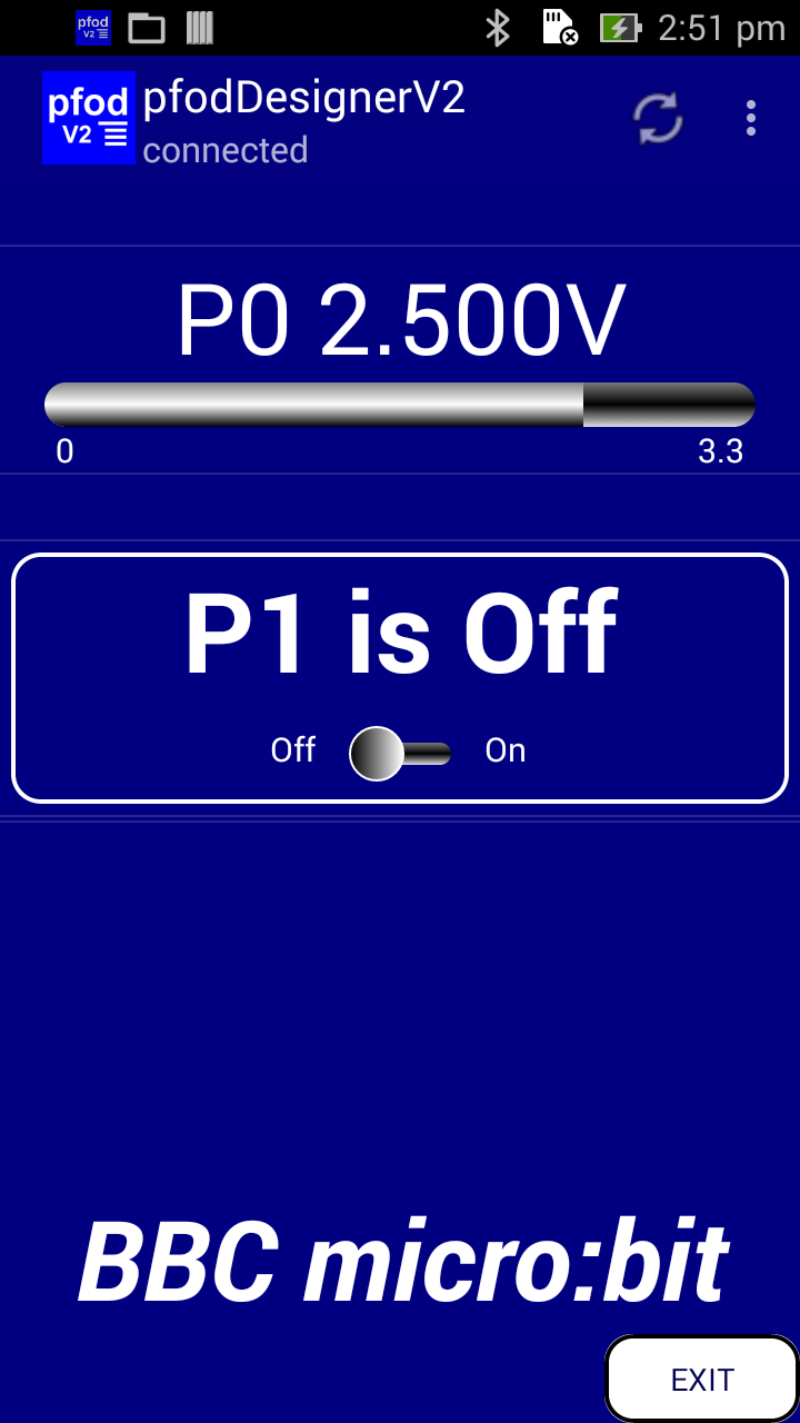
When you are satisfied with your menu design go back to Editing Menu_1 and scroll down and click on Generate Code and then click on Write Code to file and then close pfodDesignerV2 to close the code file.


This
writes a file to your mobile. You need to copy that file to your
computer and replace the exitsing pfodMenu.h and pfodMenu.cpp with
the corresponding sections from the file. There are various ways to
get the file from your android to your computer, see
pfodAppForAndroidGettingStarted.pdf
for using a USB connection. You can also use a WiFi File transfer app
like Wifi File Transfer.
Here is the generated pfodDesignerV2.txt file for the above menu design.
Now that you have the pfodDesignerV2.txt file on your computer, you need to compile it with the pfodParserMB library and the Lancaster University micro:bit support libraries. Start by following this tutorial to install the Netbeans IDE and set up the Lancaster University micro:bit C++ compiler support.
Once you have the “Hello World” program running on your micro:bit, close Netbeans and delete all the pfodtest/source files. Then install the pfodParserMicroBit zip file as described on this page.
The pfodParserMicroBit librar supplies a complete set of source files which when compiled and loaded into your micro:bit, server up a simple empty menu to pfodApp. Once you have that running as described on the pfodParserMicroBit library page you can replace the code in the pfodMenu.h and pfodMenu.cpp files with the generated code from pfodDesignerV2.txt file. Then when you re-compile and download the .hex file to your micro:bit it will serve up your custom menu when you connect with pfodApp. The complete set of source files for this menu is here.
Connecting with pfodApp displays the menu. The PO display just measure noise pickup. If you put you fingers on P0 you can vary the reading. Another thing to do is to put a clip lead between P0 and P1 and then when you turn P1 On and Off the value displayed for P0 switches between 0V and ~3.3V
This example extends the first one by adding add a chart that plots the Input Voltage on P0. The voltage is automatically logged as well on your Android mobile. This does not involve writing any C++ or Android code. There is also another pfodDesignerV2 tutorial available How to Display/Plot Arduino Data on Android which covers similar ground.
Open the pfodDesignerV2 and select Edit existing Menu and choose Menu_1. Click on Add Menu Item and scroll down and choose Chart Button.

Edit the button to your liking. Here I changed the text to “Plots” and increased the font size.

Then to edit the actual plots, Click on the “Plot” button.

Since there is only one plot at the moment, click on Edit Plot 2 scroll down and hide it. Do the same for Plot 3. Then click Chart Preview to see what the initial chart with one plot looks like.

Then go back and Edit
Chart Label to say “micro:bit
plots” and on the Edit Plot 1
screen Edit Plot Label
to say “P0 Voltage” and Edit
Plot yAxis Units to “Volts”.
Finally Edit Display Max
to “3.3” because the data range of 0 to 1023 == 0 to 3.3V
and connect this plot to micro:bit pin P0.
Then preview the chart again.

You can also go back the Edit Menu_1 screen and click Preview Menu from there to see the updated menu with the Plots button.

Clicking the Plots
button in the preview opens the sample chart you have designed. Use
the your mobile's back button to go back to the Editing
Menu_1 screen and use the Generate
Code to generate the updated
pfodDesignerV2.txt
file containing the new pfodMenu.h and pfodMenu.cpp code.
Updating the Netbeans pfodMenu.h and pfodMenu.cpp code from the new pfodDesignerV2.txt and re-compiling and dowloading into you micro:bit installs the new menu with chart. Here are the complete source files.
Now when you connect with pfodApp you see the menu with the Plots button. Clicking the plots button opens the plot of P0
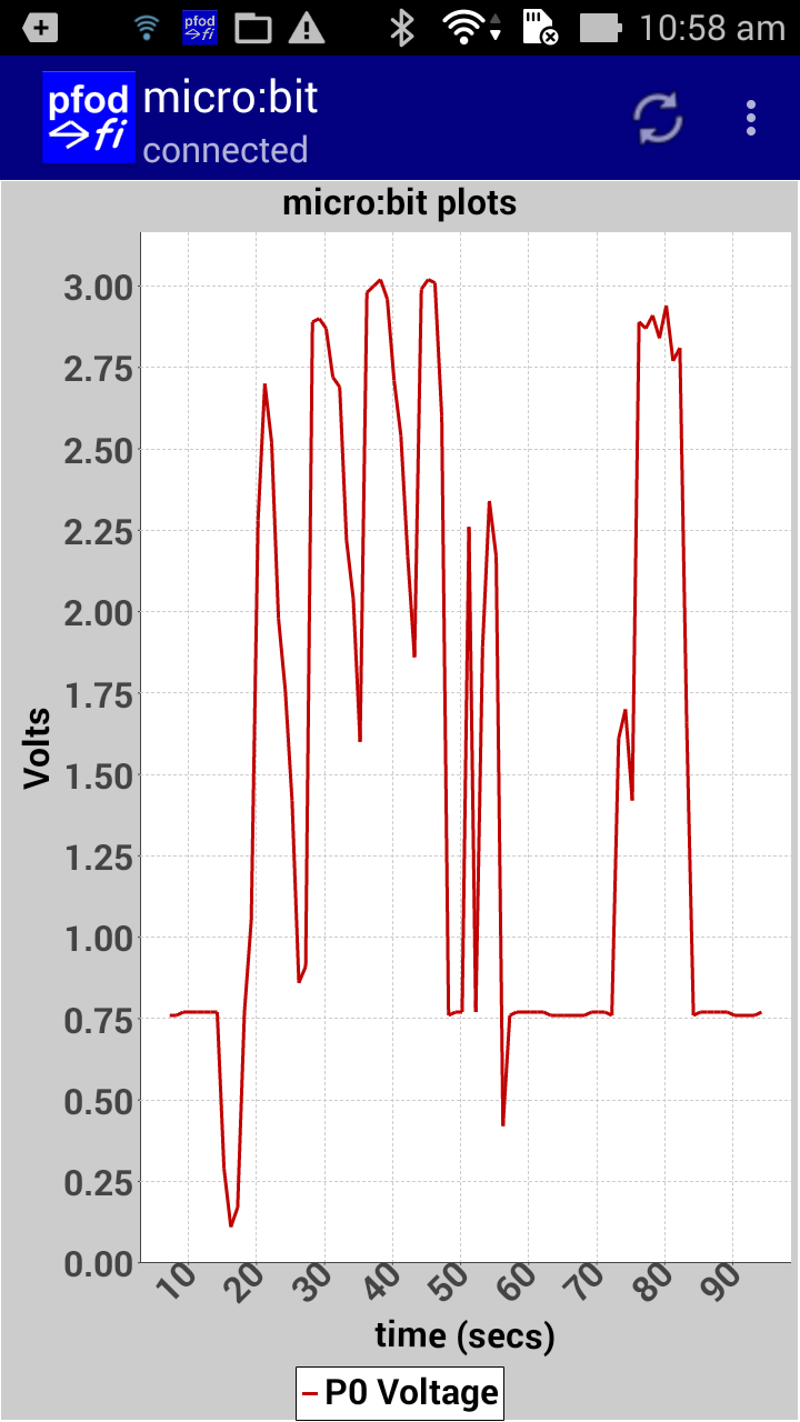
You can touch P0 with you finger to get the
plot to change. You can also connect P0 to P1 with an alligator clip
lead and drive P0 between 0V and 3.3V as you turn P1 on and off from
your mobile. The plot values are also saved in CSV format to a .txt
file on your mobile under the /pfodAppRawData
with the name you gave to your connection. As you exit pfodApp, it
will pop up a note with the data file name.
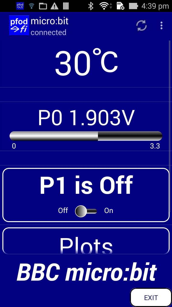
The BBC micro:bit provides a built in temperature meansurement. See https://lancaster-university.github.io/microbit-docs/ubit/thermometer/ This example adds the micro:bit's temperature to the menu and as another plot on the chart. This example involves you writing two lines of code.
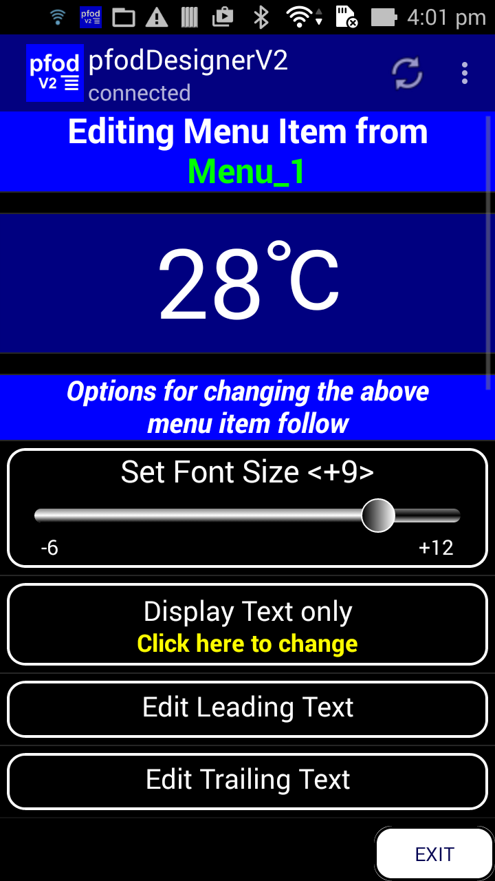
Open pfodDesignerV2 again and edit your existing Menu_1. Click Add Menu Item and choose Data Display. Edit Leading Text to delete all of it. Edit Trailing Text to ℃ pfodApp supports Unicode characters, encoded as UTF-8, so you can use non-ASCII (i.e. non-English text) and special symbols. The Unicode for ℃ is U+2103 To enter that unicode character in the Edit Trailing Text input screen you type \u2103 and as you enter the 3 the sequence will be immediately replaced by ℃
That handles the text, now you need to fix the display scaling. First set the Edit Data Variable Range. The micro:bit temperature measurement raw data is returned as degrees C (as an integer), so set the expected range, say 0 to 40 degs C. That is change the Maximum Variable Range to 40. Finally Edit Display Max to 40 to match.
Set the font size, say +9 and click on the Display Text and Slider to change it to Display Text Only, so hiding the slider display.
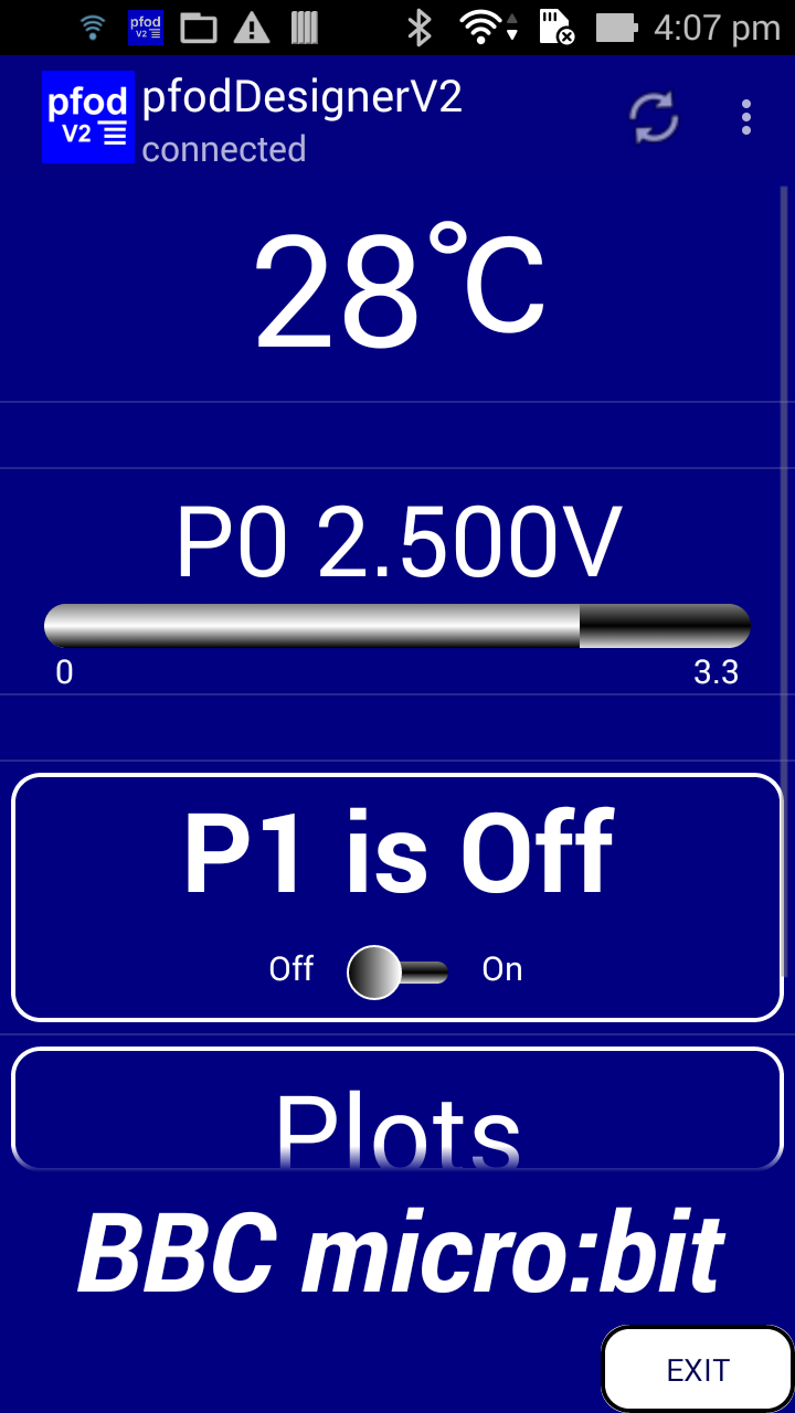
Go back
to Editing Menu_1
and
scroll down to click Move Items
Up/Down and
move the (Data
Display) the
top, above the P0. The Menu Preview now looks like this.
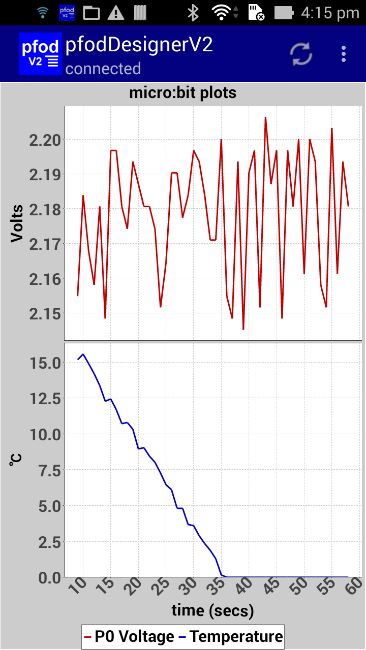
Go back to Editing Menu_1 and click on Edit Menu and click on Plots (Chart Button) and then click on the Plots button to edit the chart. Click on the Edit Plot 2 and click on Show Plot to unhide the plot. Edit Plot Label to “Temperature”, Edit Plot yAxis Units to ℃ , Edit Display Max to 40 and Edit Plot Data Variable Range to 0 to 40 as you did for the Data Display menu item above. Now when you click Chart Preview you will see.
That's the design finished. Go back to Editing Menu_1 and Generate Code again for this new menu. This is the pfodDesignerV2.txt file that is generated. Use it to update the Netbeans pfodMenu.h and pfodMenu.cpp code. Now while this new code compiles and runs, it will not show the micro:bit temperature without adding two lines of code to set the cmd_F_var and the plot_2_var to the current temperature measurement.
Open the pfodMenu.cpp file and near the top of pfodMenu::processCmd() under
    // read inputs, if any, for menu update;
    cmd_A_var = uBitPtr->io.P0.getAnalogValue();
add
cmd_F_var
= uBitPtr->thermometer.getTemperature();
And in pfodMenu::sendData() add replace
// plot_2_var= ?
withplot_2_var
= uBitPtr->thermometer.getTemperature();
That completes the necessary coding. Here is the complete set of source files for this menu. Re-compile and download to your micro:bit and re-connect your mobile to see the new menu and plots.


You may want to add a line of code to the pfodMenu::initGlobalVars() to calibrate the temperature measurement for better accuracy, using uBitPtr->thermometer.setCalibration(..)
Using pfodDesignerV2 and pfodApp, you can control and log and plot your micro:bit pins from your Android mobile without doing any coding at all. However the pfodDesignerV2 does not support all the screens and features of pfodAppV2. You should read the complete pfodSpecification.pdf for all the available options.
The General Purpose Android/Arduino Control App.
pfodDevice™ and pfodApp™ are trade marks of Forward Computing and Control Pty. Ltd.
Contact Forward Computing and Control by
©Copyright 1996-2020 Forward Computing and Control Pty. Ltd.
ACN 003 669 994