
|
Home
| pfodApps/pfodDevices
| WebStringTemplates
| Java/J2EE
| Unix
| Torches
| Superannuation
|
| About
Us
|
|
|
Inline Power Switch, Auto refresh and Blank Space for pfodApp V2™ menu
|
by Matthew Ford 7th June 2016 (originally
posted 3rd Decmeber 2015)
© Forward Computing and
Control Pty. Ltd. NSW Australia
All rights reserved.
The free pfodDesignerV2 lets you design your menus interactively and then generate the necessary Arduino sketch for a variety of boards and connection types, Bluetooth Classic, Bluetooth Low Energy,WiFi and SMS to connect via pfodApp. Sometimes you want the menu to automatically update with the latest device status and sometimes you want to add an empty, spacer, button to separate out an important button or just move the following button to the centre of the screen.
This tutorial shows you how to do both of those. How to set the menu to auto refresh and how to create that blank spacer, using pfodDesignerV2. It will also cover modifying the generated code to change the background colour as the switch state changes. As a concrete example, this tutorial builds the menu for the Inline ESP8266 controlled Power Switch.
For other tutorials on using the pfodDesignerV2 to create an Android menu system with sub-menus for Arduino Compatible devices, check out the pfodDesignerV2 main page.

For the inline power switch we only need one on/off slider button that will turn the relay on or off, we would like to have the button display more centrally on the mobile's screen. To do that we will add a blank inactive button above it. Start by downloading the free pfodDesignerV2 (V2.0.2082+) Android app.
Having install the pfodDesignerV2 app, open it and choose “Start new Menu”
From
this screen, scroll down a little and you can Change the Menu name, I
changed the menu name to “Inline Power Switch”
Then choose “Add Menu Item” and from that screen choose “Output On/Off or Pulse”. That will add a new slider menu item and open its editing screen.

Edit
this slider to change the Leading Text to Extension
Power Is and add a return at the end of
the text so that the On/Off will appear on the next line.
Edit the
Low text to Off
and edit the High text to On
Scroll
down and change the Connected pin to “Connect to D5”
since this code will be loaded onto an Olimex-EVB board which has an
on board relay driven by output D5.
Set the font size to +6, this
gives a big button to press. Pressing anywhere in the button will
toggle the power from On to Off or visa versa.
Set the font colour
to White and the background colour to Black.
Now you can test the
button by clicking on its preview at the top of the screen. As you
click anywhere in the button the slider goes from On to Off and back
again.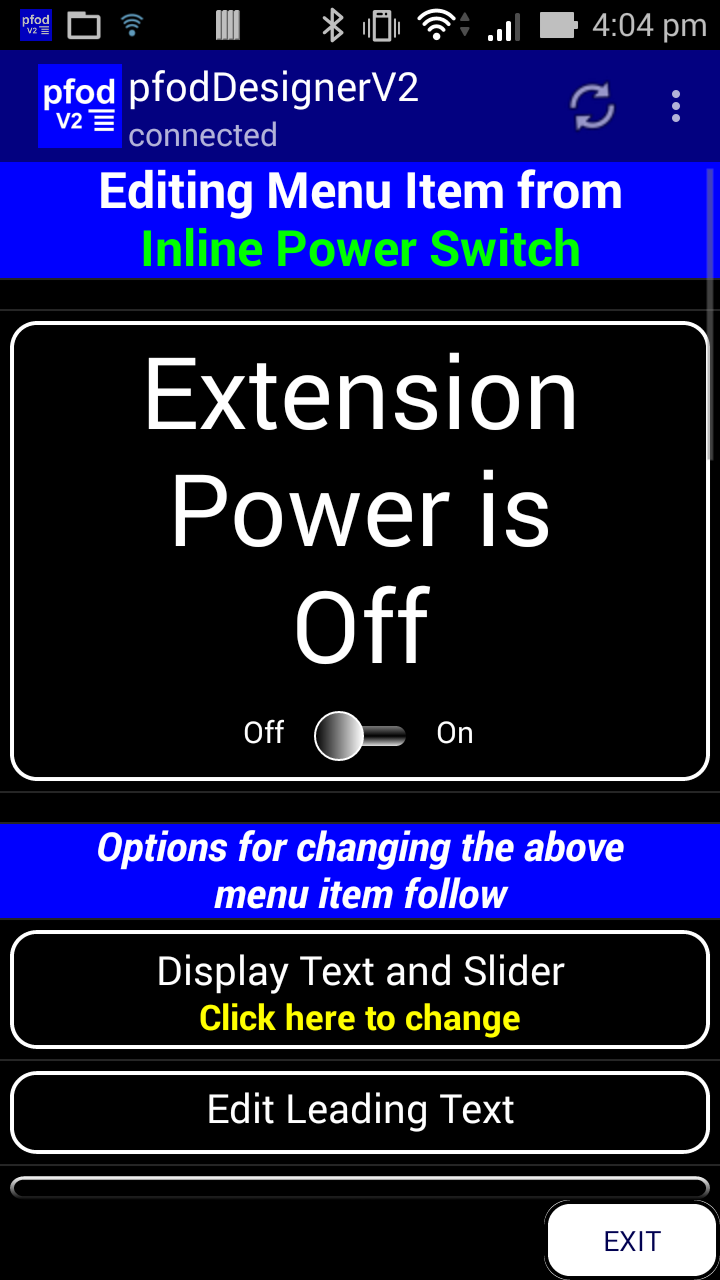
While
the button works, it would be nice to have a more visual indication
of when the power was switch on. This will be done by editing
generated code, see below, so that the menu update sets the
background red, <bg r> when the output is ON
See the
pfodSpecification.pdf for
all the available formatting.
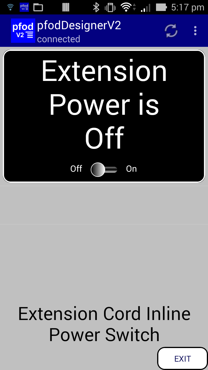
That is it for the the on/off button design. Go back to the menu editing screen and select “Preview Menu” to see what the menu will look like on your mobile. You can click anywhere in the slider button to test turning it On and Off.

Go back and Edit prompt to “Extension Cord Inline Power Switch” with font size +2 and font colour black and background silver. Then previewing the menu again shows
To position the On/Off button more centrally on your mobile's screen, you can add a blank spacer above it. Go back to the Editing screen and choose Add Menu Item, scroll down and select Label. That adds a new label to the menu and opens it's editing screen. Edit the text to delete the default “Label” text and also make the font bigger, +7.
![]()
If
you go back to the preview screen there is an invisible spacer below
the On/Off button. To move this up above the On/Off button go back to
the menu Editing screen and scroll down to find the “Move Items
Up/Down”

Click
on the “Move Items Up/Down button to show the two menu items
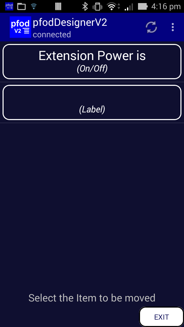
Click the blank (Label) button to select it and the move to screen is displayed.
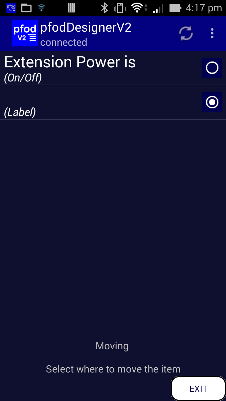
Select the Extension Power is item to move the blank spacer to that position. i.e. Make the space the first item in the menu. The updated move to screen is then displayed and you can use the back button to go back menu Editing screen and select Preview Menu again.

This shows the On Off button moved towards the centre of the screen. You can adjust the font size of the blank spacer to make the spacer larger or smaller as you wish. You can also add newlines to expand the spacer. On the preview screen you can check that clicking in the spacer does nothing while the clicking in the on/off button changes the Power from On to Off and changes the background colour.
By default, pfodApp only requests the menu when you open it or send a command. However sometimes you what the menu to refresh at a regular interval in order to display any status changes on the remote pfodDevice. In the case of the Inline Power Switch, the generated sketch is going to be modified to add a manual push button input to turn the power on and off from the device. So in order to display this local manual override on the remote pfodApp, pfodApp needs to regularly re-request the menu to display the current setting, On or Off.
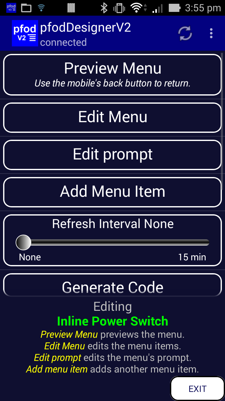
To set the refresh interval go back to the Editing screen and set the Menu Refresh Interval to 1sec. as shown below.
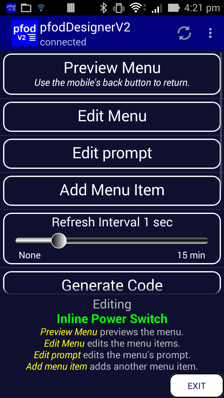
Once your menu design is complete, you can generate the Arduino sketch that will display this menu on pfodApp and allow you to turn D5 on and off from the on/off button.
From the Editing menu screen and select Generate Code. Click on the Change Target button change the selection.
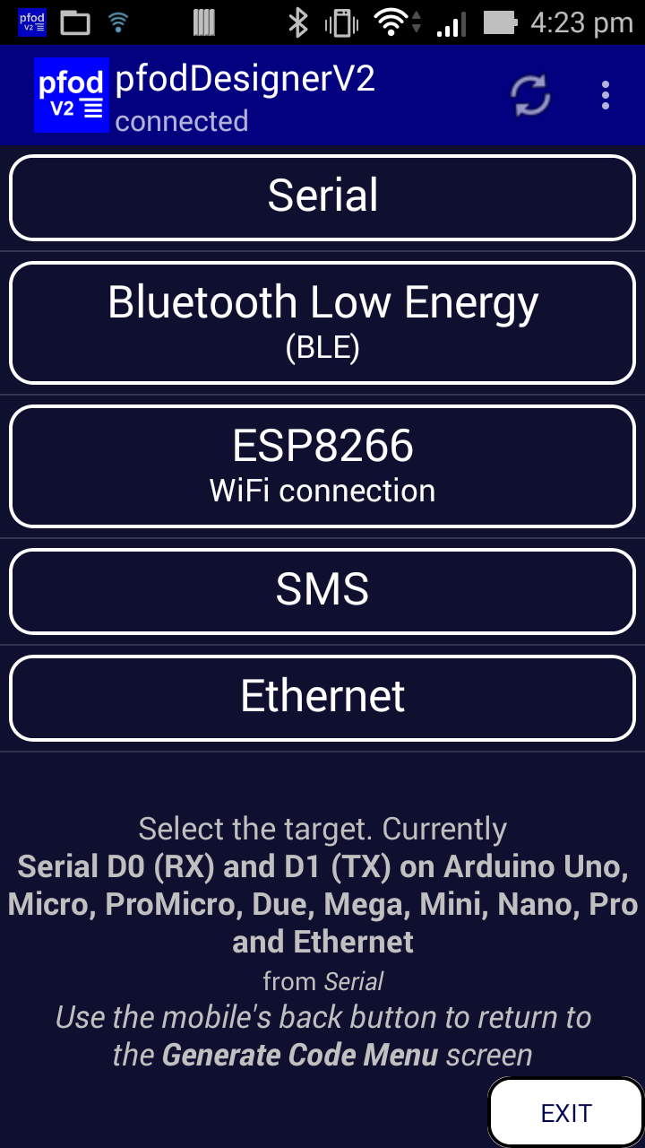
and
select ESP8266 Wifi connection as the target device and then choose
the (only) option, ESP8266 programmed via Arduino IDE option
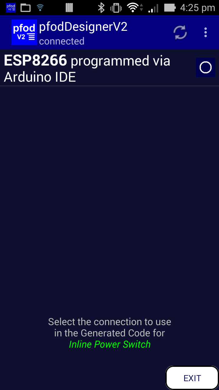
Then
go back to the Generate Code Menu Screen

Then
click on Write Code to file to generate and write the sketch suitable
for ESP based devices. In this case an Olimex-EVB board with a
built-in relay controlled by D5

As
shown in the screen shot, the generated code is written to a file on
your mobile /pfodAppRawData/pfodDesignerV2.txt
You need
to transfer this file to your computer to program your device using
the Arduion IDE. I use a WiFi
File Transfer app to do the transfer. The generated
sketch is here.
To compile this sketch you will need to install two libraries, pfodParser.zip and pfodESP8266BufferedClient.zip , from pfod Parser Libraries page Then follow the instructions on Code Generator for OLIMEX ESP8266-EVB to install the ESP8266 board support for Arduino V1.6.8 and program the OLIMEX-EVB board.
As generated the code will display the menu on your Android mobile and switch the OLIMEX relay on and off as you click the button. As noted above we would like the button's background to be updated to RED when the power switch is on. To do that we need to modify the code that sends the main menu and the update.
Here are the two methods the need to be modified
void sendMainMenu() {
  // !! Remember to change the parser version string
  //    every time you edit this method
  parser.print(F("{,"));  // start a Menu screen pfod message
  // send menu background, format, prompt, refresh and version
  parser.print(F("<bg w><+2><bk>~Extension Cord Inline Power Switch`1000"));
  parser.sendVersion(); // send the menu version
  // send menu items
  parser.print(F("|!B<+7>"));
  parser.print(F("~"));
  parser.print(F("|A<bg bk><+6><w>"));
  parser.print('`');
  parser.print(cmd_A_var); // output the current state 0 Low or 1 High
  parser.print(F("~Extension Power is\n~~Off\\On~"));
 // Note the \\ inside the "'s to send \ ...
  parser.print(F("}"));  // close pfod message
}

void sendMainMenuUpdate() {
  parser.print(F("{;"));  // start an Update Menu pfod message
  // send menu items
  parser.print(F("|A"));
  parser.print('`');
  parser.print(cmd_A_var); // output the current state 0 Low or 1 High
  parser.print(F("}"));  // close pfod message
  // ============ end of menu ===========
}
When the cmd_A_var is 1 we want to add <bg r> after the |A
command to set the background to red when the switch is on. The
revised methods are:-
void sendMainMenu() {
  // !! Remember to change the parser version string
  //    every time you edit this method
  parser.print(F("{,"));  // start a Menu screen pfod message
  // send menu background, format, prompt, refresh and version
  parser.print(F("<bg w><+2><bk>~Extension Cord Inline Power Switch`1000"));
  parser.sendVersion(); // send the menu version
  // send menu items
  parser.print(F("|!B<+7>"));
  parser.print(F("~"));
  parser.print(F("|A"));
  if (cmd_A_var == 1) {
    parser.print(F("<bg r>")); // red if on
  } else {
    parser.print(F("<bg bk>")); // black if off
  }
  parser.print(F("<+6><w>"));
  parser.print('`');
  parser.print(cmd_A_var); // output the current state 0 Low or 1 High
  parser.print(F("~Extension Power is\n~~Off\\On~"));
 // Note the \\ inside the "'s to send \ ...
  parser.print(F("}"));  // close pfod message
}

void sendMainMenuUpdate() {
  parser.print(F("{;"));  // start an Update Menu pfod message
  // send menu items
  parser.print(F("|A"));
  if (cmd_A_var == 1) {
    parser.print(F("<bg r>")); // red if on
  } else {
    parser.print(F("<bg bk>")); // black if off
  }
  parser.print('`');
  parser.print(cmd_A_var); // output the current state 0 Low or 1 High
  parser.print(F("}"));  // close pfod message
  // ============ end of menu ===========
}
Finally change the version number at the top of the sketch so the
pfodApp knows to its cached menu is not the current one. Here I have
just added 'm' for modified to the current version. The
pfodDesignerV2 automatically updates the version number each time it
generates the code.
pfodSecurity parser("V3m"); // create a parser to handle the pfod messages
The completed modified sketch is here, InlinePowerSwitch.ino
With these modifications the button background changes to red when the switch is ON
This tutorial showed you how to use pfodDesignerV2 to add a blank spacer to a menu, how to set an auto refresh interval to regularly update the menu with the latest device status and how to modify the generated code to change the background colour with the switch state. The example used was the design of a menu for OLIMEX-EVB ESP8266 based board which will used for the InlineWiFiPowerSwitch. The InlineWiFiPowerSwitch page will show show the hardware is constructed and how this generated code is modified to add a push button input and to add a web page config to set your network parameters.
pfodDesignerV2TM
is a trademark of Forward Computing and Control Pty. Ltd.
AndroidTM
is a trademark of Google Inc. For use of the Arduino name see
http://arduino.cc/en/Main/FAQ
The General Purpose Android/Arduino Control App.
pfodDevice™ and pfodApp™ are trade marks of Forward Computing and Control Pty. Ltd.

Contact Forward Computing and Control by
©Copyright 1996-2020 Forward Computing and Control Pty. Ltd.
ACN 003 669 994