
|
Home
| pfodApps/pfodDevices
| WebStringTemplates
| Java/J2EE
| Unix
| Torches
| Superannuation
| CRPS Treatment
|
| About
Us
|
|
|
BLE Door Bell
|
by Matthew Ford 6th January 2025 (original 6th January 2025)
©
Forward Computing and Control Pty. Ltd. NSW Australia
All rights
reserved.
This project is a simple BLE door bell for beginners with the
option to retrofit an old (broken) RF door bell for experienced
constructors. This BLE doorbell, while still running for years on a
coin cell, has a number of advantages over the RF alternatives:-
*
It is immune to interference from other doorbells in the
neighbourhood.
* You can choose your own tune to play when the
button is pressed
* You can have multiple monitor/receivers
responding to the doorbell press button.
* It remembers when the
door bell was pressed when you were out and displays a flashing
led.
* You can monitor a front and back door press button with one
(or more) monitor/receiver and optionally have different tunes for
each door
* You can add up to four (4) extensions to monitor the
door bell over the wifi.
* Beginners can safely complete this
project by using an encased USB supply and a small plastic box for
the monitor/receiver and extensions.
When the existing RF doorbell failed, the first choice was to just replace it with a new one. However over 50% of the reviews of RF doorbells were negative, complaining of interference from other RF doorbells in the neighbourhood that caused the bell to sound when no one was at the front door. We had also noticed that ourselves prior to doorbell failing. So instead of buying a new RF doorbell, the previous BLE Window Open Detector project was repurposed as a doorbell. The components were small enough to fit in the existing push button case and door bell receiver. However you can also use a small waterproof box for the doorbell and a plastic box for the receiver.
Prices as at January 2025 excluding shipping.
BLE Door Bell
1 x nRF523832
module such as Jessinie XL52832-D01 nRF52832 module ~US4.90 and
Jessinie Test Board Adapter Plate for NRF52832 ~US$1.70 – Total
~US$5.60 (Aliexpress)
OR
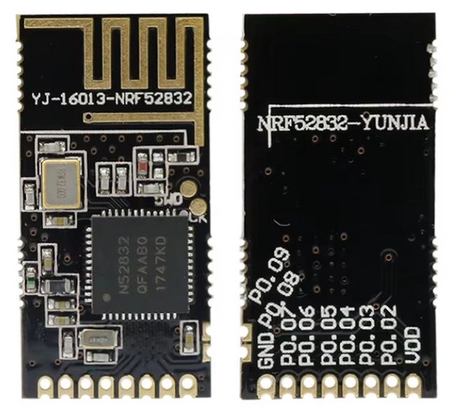
Holyiot YJ-16013-NRF52832 OR (in this build) Holyiot nRF52832 –
YJ-16048 ~US$5.00 (Aliexpress)
1 x CR2032 coin cell ~ US$1.00
1
x Aokin CR2032 Battery Holder – US2.51 for 10 off
(Aliexpress)
1 x PCB or veroboard to suit nRF523832 module (see
BLE Window
Open Detector for the pcb used in this build)
1 x Momentary
Pushbutton (weather proof) – if not retrofitting an existing
door bell e.g. Jaycar CAT.NO:
SP0732 ~US$4.40
1 x ABS plastic box (weather proof) – if
not retrofitting an existing door bell e.g Jaycar CAT.NO:
HB6124 ~US$8.70
Door Bell Receiver and Extension (One set for
receiver and one set for Extension)
1
x Dfrobot
Beetle ESP32-C3 ~US$7.90
1 x Dfrobot
Voice Prompt Module with Integrated MP3 Player and Speaker
~US$7.90 OR buzzer e.g. Jaycar
Mini Piezo Buzzer 3-16VDC ~US$2.80
1 x USB supply e.g. Dfrobot
5V 1A ~US$3.40
1 x clear plastic box – if not
retrofitting to existing door bell receiver. e.g. Jaycar CAT.NO:
HB6005 ~US$2.40
The circuit for the BLE Door Bell Push Button is trivial. The circuit below is for a Jessinie module (pdf version)

The YJ-16013-NRF52832 version uses the same pins, while the
YJ-16048 on the BLE
Window Open Detector PCB uses pin 11 for the LED.
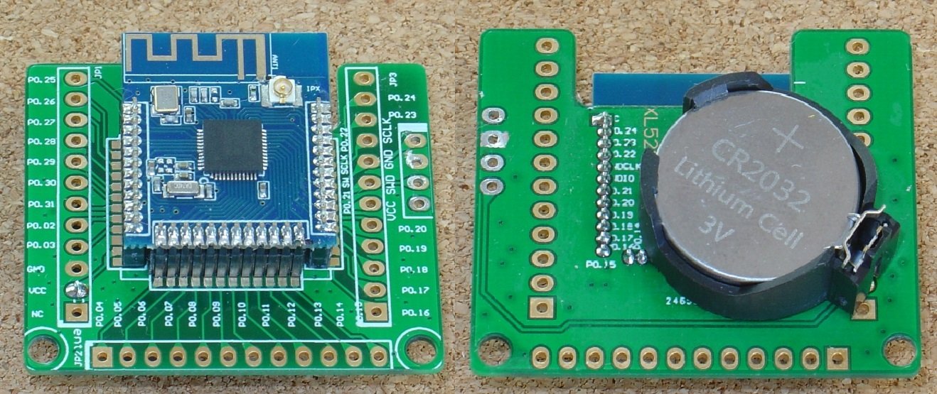
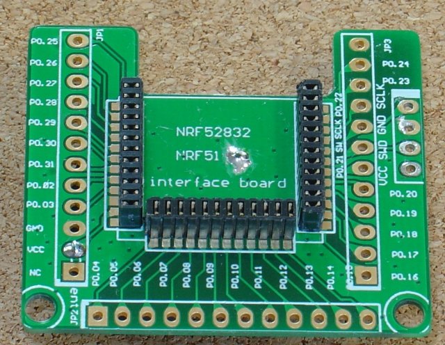
If you are making your own door bell, you can use any suitable 'bare board' nRF52832 module such as Jessinie XL52832-D01 nRF52832 module and Jessinie Test Board Adapter Plate
The
the coin cell can be mounted on the back of the board between the VCC
pin and hole drilled in the centre earth plain. Mount it in a small
box weather proof box with a push button and optionally an indicator
Led
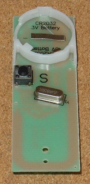
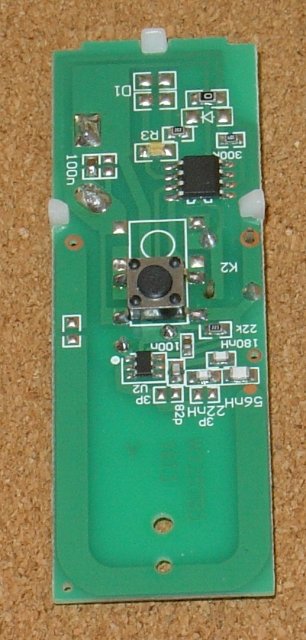
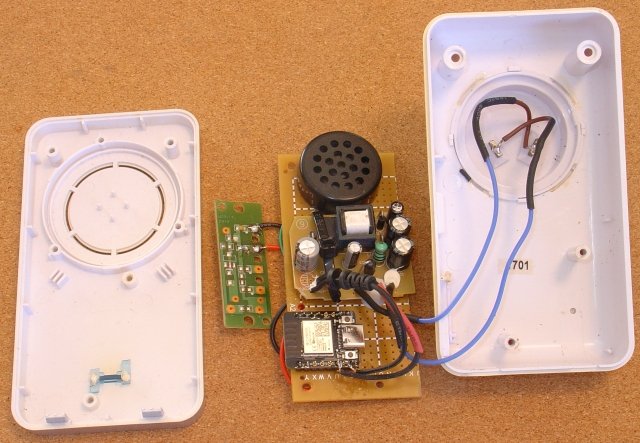
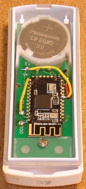
Here the existing doorbell was refitted with a BLE module. The existing doorbell button is stripped of most of it components, except for the battery holder, led and its resistor and the main push button. A small nRF52832 module is then added to broadcast “Front_Door” when the button is pressed.
Before removing the components, the doorbell led and its series resistor was identified and the led polarity determined with a multimeter on diode mode. The led and its series resistor is kept when the other components are removed.
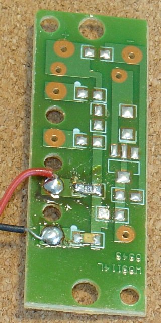
Tracing the track on the doorbell PCB gives the layout below (pdf version) Apart from the battery connections (Bat -v and Bat +v) there are only two other connections. One from the push button to nRF25832 pin 2 (A0). The push button connects to the +V when pressed. The other is the output to drive the led indication when the button is pushed. The +ve side of the led is connected to Bat +v, on the pcb, via a series resistor. The negative side of the led is connected to the ble module, either pin 7 or pin 11 as convenient.
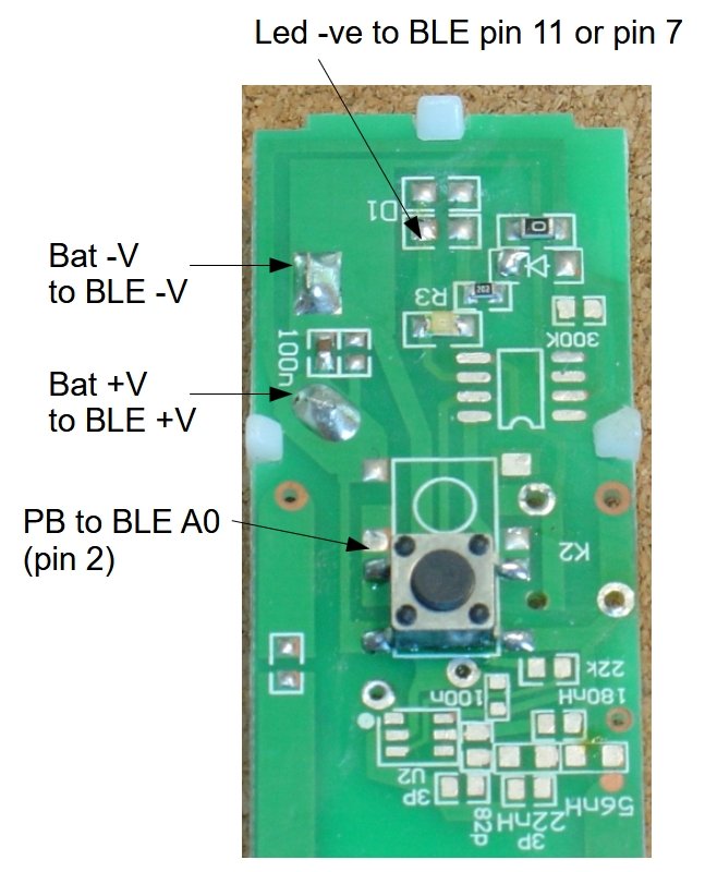
In this construction a PCB from the BLE Window Open Detector was used trimmed to fit and pin 11 was used to drive the led. However you can also a piece of veroboard to mount a YJ-16013-NRF52832 module and use pin 7 to drive the led.
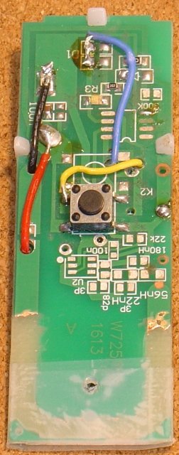
Here is the completed bell button wiring. Note that the tracks at the bottom of the original push button board have been scrapped off so as not to interfere with the BLE module's antenna,
Install the pfod_lp_nrf52_2024 Arduino board support as described in Easy Very Low Power BLE in Arduino
The sketch is lp_BLE_DoorBell.ino
and the SafeString
library (from the Arduino library manager)
Near the top of the
sketch set the led pin. It is currently set to pin 7, assuming you
are using an YJ-16013-NRF52832 or Jessinie module and a piece of
veroboard.
Each door should be assigned a unique name. Set the LOCAL_NAME at the top of the sketch.
const char LOCAL_NAME[] = "Front_Door";
When programming the module, it is best to solder the power and SWCLK and SDO cables directly to board and programmer. Jumper cables are convenient but become unreliable after repeated use.
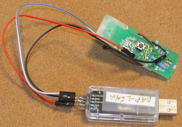

If you are using the YJ-16013-NRF52832 module, the SWCLK (CK) and SDO (SWO) are pads on the board rather than edge connectors.
To have a front and back door bell, build a second BLE doorbell push button and set the LOCAL_NAME to “Back_Door” and add the second name to the expectedDevices in the DoorBell_ESP32C_Monitor_Server.ino sketch below.
char expectedDevices[][MAX_BLE_ADVERTISED_NAME] = { "Back_Door", "Front_Door" };There are two options here:-
If you are a beginner, then the
safe approach is to just mount the Dfrobot Beetle ESP32-C3 and MP3
speaker on a piece of veroboard in a small plastic box and power it
via a USB supply and cable so that you are only exposed to 5V
voltages.
If you are an experienced constructor who understands
the dangers of working with Mains Power, you can build the receiver
into the existing case using a power board from a USB supply.
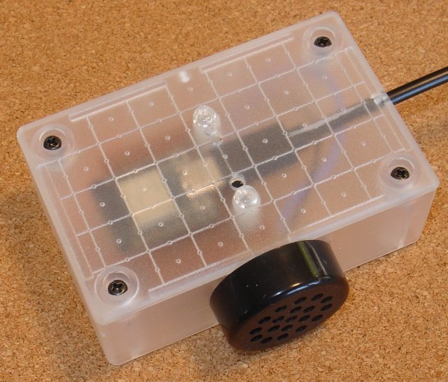
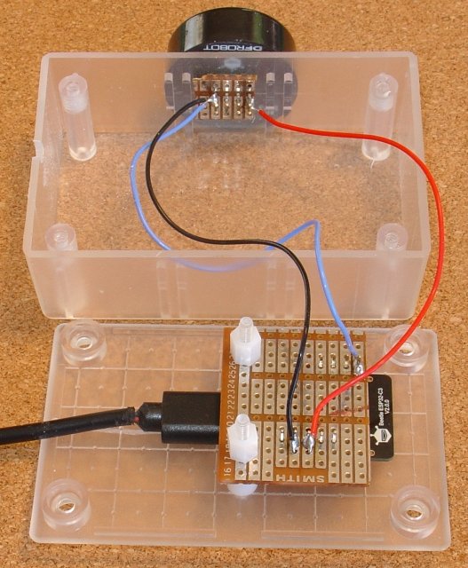
The low voltage monitor consists of just an Dfrobot Beetle ESP32-C3 and an MP3 speaker (shown here) or buzzer, powered by a USB supply. The MP3 speaker pins pass through holes in the plastic case and a small piece of veroboard is soldered to the MP3 speaker pins to secure the speaker in place.
Again the circuit is trivial (pdf version)
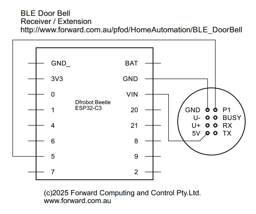
If using a buzzer instead of the mp3 voice module, then connect the buzzer between pin 6 and GND. The Dfrobot Beetle ESP32-C3 has a built-in led on pin10 which is used as the indicator.
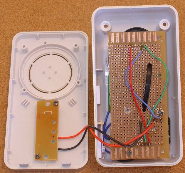
Retrofitting an existing doorbell receive involves mains power wiring and so should only be attempted by experienced constructors aware of the fatal dangers of main power.
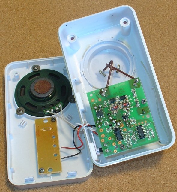
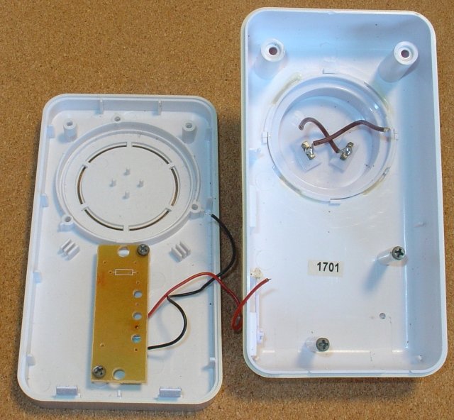
The speaker and main pcb of the existing receiver are removed. The led board is kept and an 820R resistor added in series with the led so it can be driven by Pin 4 of the Dfrobot Beetle ESP32-C3.
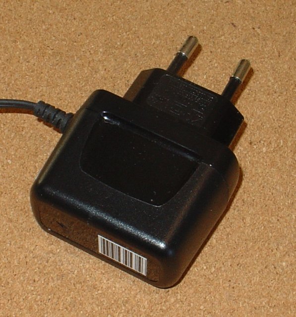
To power the receiver, the power board from a USB supply was used an its mains power leads wired to the power pins of the in the receiver case.
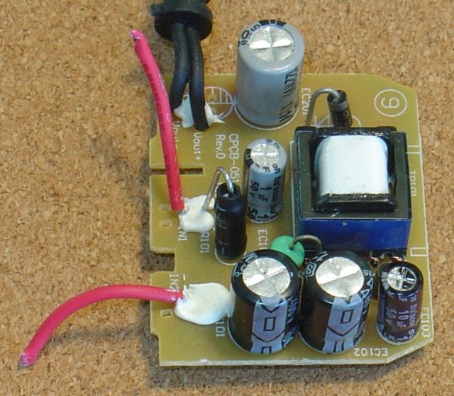
A piece of veroboard is used to mount MP3 speaker and USB supply board and the Dfrobot Beetle ESP32-C3 board in the original case. The modified led board is used as the indicator led.
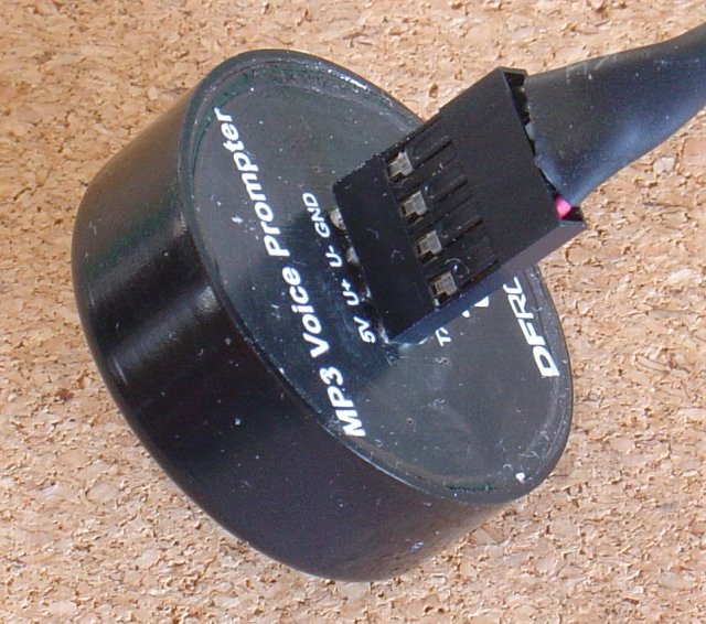
Before wiring up the MP3 speaker, load it with the tune .mp3 file you want played when it the door bell is pressed. As delivered the Voice Prompt Module has two files. Plug in the USB cable (supplied with the speaker) as shown here. NOTE Carefully: the red lead goes to the 5V pin and the silver side of the plug faces the 5V... GND labels.
The
MP3 speaker will appear as a disk drive on your computer. Delete the
two .mp3 files and copy your tune as 001.mp3.
An example prompt file is here
(See the next section for how to make your
own.)
To
test the tune touch the P1 pin to the GND lead.
Once you have loaded your tune and tested it, you can wire it into the board. Be very careful when wiring up the Voice Prompt module to correctly connect the 5V and GND pins.
Install Audacity from https://www.audacityteam.org/download/ No extra libraries or add-ons are needed for this project.
To make your own tune, choose an alarm tone from one of the many
freely available on the internet. Search for “free alarm
tones”. Avoid those with low frequency components as the Voice
Prompt Module does not render low frequencies.
Load the alarm into
Audacity and then export it as a MONO file. Reload it and cut it to
the desired length, adjust its volume and save it again for loading
on the MP3 speaker
Install the
ESP32 board support V3.0.7 (other versions may not work)
See
https://docs.espressif.com/projects/arduino-esp32/en/latest/installing.html
for instruction. Choose V3.0.7 from the drop down version.
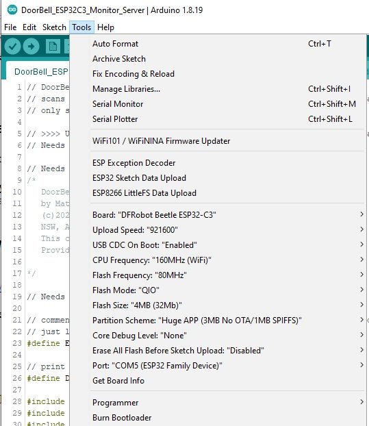
Select
the board Dfrobot Beetle ESP32-C3 as the board to program.
Plug in
the board, if you don't see the COM port in your Arduino IDE you need
to install the ESP32
CP201x USB to UART bridge VCP drivers
Set the USB CDC On Boot: “Enabled” and the Partition Scheme: “Huge APP (3MB No OTA/1MB SPIFFS)”
Unzip DoorBell_ESP32C3_Monitor_Server.zip to your Arduino sketch directory and install the SafeString and ESPAutoWiFiConfig libraries (available from Arduino library manager)
The
char expectedDevices[][MAX_BLE_ADVERTISED_NAME] = { "Back_Door", "Front_Door" };at the top of the sketch needs to match the LOCAL_NAMEs you set in the lp_BLE_DoorBell.ino sketches for your door bells. Here a front and back door are monitored. Just delete the “Back_Door”, entry if you only have a front door bell.
Choose the appropriate pin to drive the indicator led. Pin 4 for the retrofit OR Pin 10 for the built-in led if making the low voltage version.
const int LedPin = 4; // 4 for external led OR 10 for Dfrobot Beetle ESP32-C3 BUILT-IN led
The DoorBell_ESP32C_Monitor_Server sketch provided has DEBUG enabled to print out debug messages. Comment out the #define DEBUG when you are finished check the operation.
To setup the monitor/reciever plug it in and after 30sec the led will start flashing rapidly indicating it could not connect to the WiFi network and has set up its own Access Point for you to connect to in order to configure the IP address and network SSID and password. See ESPAutoWiFiConfig for all the details. You can use an IP scanner program like Angry IP Scanner to see what IPs are already in use on your network. Choose a free one in the range x.x.x.200 to x.x.x.253 as these higher numbers are less likely to be pre-assigned.
Once the IP address and network
access have been configured the monitor will reboot after a 30secs.
Press the door bell button and check the tune / buzzer sounds. Move
the monitor closer if is not detected.
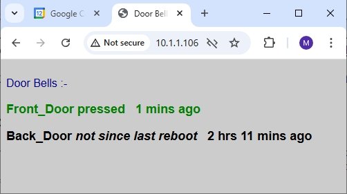
Open the monitor's webpage
http://10.1.1.106 for example if you
set 10.1.1.106 as the monitor's IP and you will see a list of the
door bells being scanned for and when they were last seen.
The
DoorBell_ESP32C_Monitor_Server sketch scans for the expected
BLE devices. When one is seen the
time is recorded and the tune or buzzer is sounded and the led is set
to flash slowly. When you return after being out, if the led is
flashing slowly you know the door bell was pressed while you were
away. You can then open the monitor's webpage to see which button was
pressed and how long ago. Opening the monitor's web page also turns
off the flashing led.
When a door bell is pressed the
monitor's led starts flashing slowly. When you open the web page it
cancels the flashing, so close the webpage after checking.
The DoorBell_ESP32C_Monitor_Server also provides a telnet server that up to 4 extension clients can connect to the provide remote door bell alerts.
If you don't want to connect the door bell to your WiFi network just comment out the #define ENABLE_WIFI at the top of the DoorBell_ESP32C_Monitor_Server.ino sketch.
The BLE DoorBell has a range of about 30m un-obstructed and so should work in most homes. However for longer range monitoring you can use an extension monitor which connect via telnet to the main monitor/receiver. This lets you add up to four (4) monitors in remote locations, like the back shed.
The construction is exactly the same as the for the Safe Low Voltage Monitor above.
As for the
main monitor
Install the ESP32 board support V3.0.7 (other
versions may not work)
See
https://docs.espressif.com/projects/arduino-esp32/en/latest/installing.html
for instruction. Choose V3.0.7 from the drop down version.
Select
the board Dfrobot Beetle ESP32-C3 as the board to program.
Plug in
the board, if you don't see the COM port in your Arduino IDE you need
to install the ESP32
CP201x USB to UART bridge VCP drivers
Set the USB CDC On Boot: “Enabled” and the Partition Scheme: “Huge APP (3MB No OTA/1MB SPIFFS)”
Install
the SafeString
and ESPAutoWiFiConfig
libraries (available from Arduino library manager)
open the
DoorBell_ESP32C3_Extension.ino
sketch and edit the line to set the IP to match one your
monitor/receiver has been install on. For example
const char* DoorBell_host = "10.1.1.106"; // DoorBell_ESP32C3_Monitor_Server bridge
Then program the Dfrobot Beetle ESP32-C3 with the modified sketch.
Install the Extension Monitor using ESPAutoWiFiConfig to set its IP and network SSID and password. The extension will make a telnet connection to the main monitor and when the door bell is pressed the main monitor will send a message to the extension to play the tune / sound the buzzer and set the led to slowly flash. When you open the web page of the main monitor, e.g. http://10.1.1.106 (not the extension), the led flashing will stop.
The MP3 speaker can play more than just one tune. The tune to be
played can be select via the MP3's serial connection (9600 baud). See
section 4 Serialport command explanation of the instruction
manual (local
copy here)
ESP32–Tx connects to MP3 speaker-Rx and
ESP32-Rx connects to MP3 speaker-Tx.
For Track 1 (001.mp3) use
const
uint8_t track1[] = { 7E, 03, 00, 02, 00, 01, EF};
For Track 2 (002.mp3) use
const
uint8_t track2[] = { 7E, 03, 00, 02, 00, 02, EF};
and send the track to the serial
connection. E.g. for track 1 use
Serial.write(track1, 7);
This BLE Doorbell uses only a couple of components and is simple to construct by beginners and is immune to the RF interference from 'standard' doorbells. Experienced constructors can retrofitted an existing RF doorbell. It uses a very low power BLE module in the press button to notify the monitor when the button is pressed. You can monitor multiple push buttons and can choose your own tune/announcement to be played by the MP3 speaker. The monitor remembers when the button was pressed and a flashing led alerts you when you return home. A web page shows which button was pressed and how long ago.
A simple extension monitor was also presented when connects over WiFi to the main monitor to provide remote alerts and flashing indications.
Android TM is a trademark of Google Inc. For use of the Arduino name see http://arduino.cc/en/Main/FAQ
The General Purpose Android/Arduino Control App.
pfodDevice™ and pfodApp™ are trade marks of Forward Computing and Control Pty. Ltd.

Contact Forward Computing and Control by
©Copyright 1996-2024 Forward Computing and Control Pty. Ltd.
ACN 003 669 994