|
Home
| pfodApps/pfodDevices
| WebStringTemplates
| Java/J2EE
| Unix
| Torches
| Superannuation
|
| About
Us
|
|
|
pfodDesignerV2™
|
by Matthew Ford 4th June 2016 (originally
posted 28th August 2014)
© Forward Computing and
Control Pty. Ltd. NSW Australia
All rights reserved.
The project is suitable for complete beginners. No coding experience is required. This tutorial does not require any soldering. Once you have finished this tutorial you will be able to design whatever menus you need to switch Arduino outputs on and off.
This tutorial that shows you how to use the free pfodDesignerV2 available on GooglePlay to design Android menus to switch Ardunio outputs on and off from your Android mobile, without you having to write any program code at all.
The menus are completely customizable. You can change the text, color and font size as well as selecting the Arduino output to be controlled. All using the pfodDesignerV2 running on your Android mobile. The pfodDesignerV2 gives you an exact preview of how your menu will display when you connect using pfodApp . No Android Programming is required.
When you have finished designing your menu, the pfodDesignerV2 generates a complete, well commented, Arduino sketch that will implement your menu and allow you to turn the outputs on and off via your mobile using the pfodApp (via bluetooth or wifi). No Arduino Programming is required.
As part of the design you specify which digital output to the On/Off Toggle button is connected to. For the UNO board used here and most other Arduino boards D13 is connected to the LED.
This project is suitable for complete beginners but you need complete a few tasks before you start. You need to first set up the Arduino IDE, install pfodDesignerV2 and make sure you can transfer the final sketch (code file), that pfodDesignerV2 produces, from your mobile to your computer.
a) Install the Arduino IDE for your computer's operating system from Getting Started with Arduino and work through the example of compiling and running the Blink example.
b) Install the free pfodDesignerV2 app on your Android mobile.
c) Check that you are able to transfer files from your mobile to your computer either via a USB cable or a file transfer app such as WiFi File Transfer. See pfodAppForAndroidGettingStarted.pdf for more details.
The pfodDesignerV2 is free so you
can do most of this tutorial with just that pfodDesignerV2 on your
Android mobile. But if you want to actually switch something on or
off you will need some hardware and the pfodApp.
Here is a complete parts list.
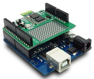
You need an Arduino board. The tutorial uses an Arduino Uno.
You need a wifi or bluetooth or BLE shield so your Android
mobile can connect to the Uno. This tutorial uses Itead
BT Shield Bluetooth V2 which connects via Serial at 9600 baud. If
you are doing the BLE
tutorial check the steps there after designing the menu
here.
Finally to test your design, you need to download
pfodApp
from GooglePlay
to connect your Android mobile to the Uno via the bluetooth (or wifi
or BLE) shield and display the menu you have designed for you to
control the Arduino LED. See pfodAppForAndroidGettingStarted.pdf
for how to set up a bluetooth connection in pfodApp.
This tutorial will design a custom menu on an Android phone to turn the Arduino LED on and off. The LED is controlled by output D13 on most, but not all, boards. Here is what the final menu will look like, but you can choose your own text and colors and font sizes using the pfodDesignerV2.

Download and install pfodDesignerV2 from GooglePlay.
On opening pfodDesignerV2 you will be presented with the Start new Menu button. Each screen also has a Help button.

or
if you have already started a menu you will also see an option to
Edit existing Menu
will also
be available

Clicking
the Start new Menu
button displays a list of operations available for the new menu. A
new menu is created with no buttons and a default menu name, Menu_1
If you want the pfodApp to
re-request this menu at regular intervals to get the latest values,
then set a “Refresh Interval” using the slider shown
above.
Click Preview Menu
to see what the current design looks like. No buttons yet, just some
default prompt text at the bottom.
Use the mobile's back button to go back to the Editing screen to edit the default prompt to something more useful.
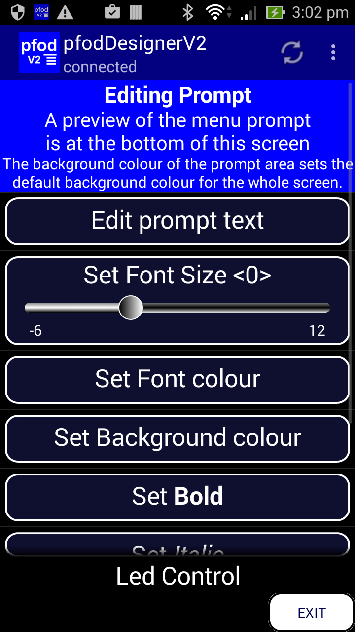
Click on Edit Prompt to open the Editing Prompt screen. The prompt is the text displayed to the user at the bottom of the scrollable list of menu buttons. In the Editing Prompt screen, a preview of the prompt is shown at the bottom of the screen.
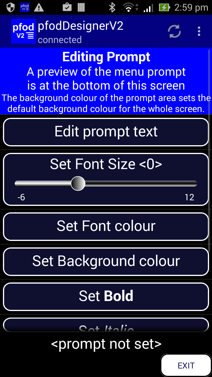
Click
Edit prompt text
and set the text to “Led Control”, pfodApp will
automatically warp the text if it too wide for the screen, or you can
manually add a newline between 'Led' and 'Control' to force the text
on two lines.
Click
the tick box to accept these changes and re-display the Editing
Menu Prompt screen with the updated
prompt text, at the bottom of the screen.
Then
set the font size to <+7>, font colour to Red, background
colour to Navy and set Bold. (Scroll down to access the other
formatting options)
Use the mobile's back button to go
back to the Editing
screen and click Add Menu Item
to add the first button to this menu. This will display a series of
choices, (scroll down for more options):-
There
are a number of different types of menu items. In this tutorial we
are using an On/Off Slider to toggle a digital output pin on an
Arduino board, so select the Output
On/Off or Pulse. See Android
menu buttons for Arduino made Simple for a tutorial on using
plain menu buttons. See Design
a Custom Menu System for a tutorial that uses the Sub-menu
item.
Selecting the
Output On/Off option opens the Changing
Menu Item screen for the item just
added.
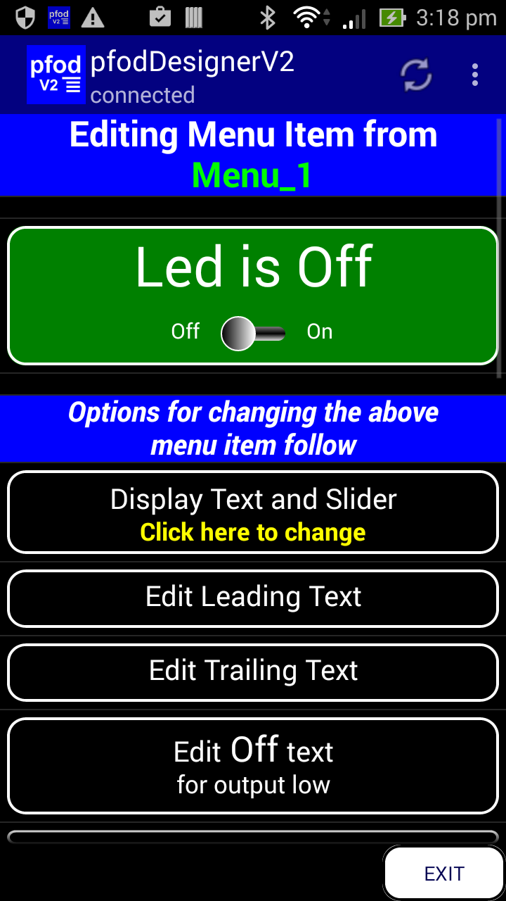
The “Low” state sets the Arduino output to zero Volts, while the “High” state sets the output to the Arduino +Vcc, usually +5 or +3.3V depending on the Arduino board. Uno boards are +5V.

The
text displayed on the button consists of the Leading Text followed by
the current state and then the Trailing Text. The default leading
text is “Output is”, the default trailing text is “”
and a current setting is Low, so the button will display “Output
is Low”. You can edit all these texts to suit your own use.
You can move the preview's slider left or right to change the current setting in the preview, but it is easier to just click anywhere in the button to see how it toggles.
This On/Off toggle button can be set to control a particular Arduino digital output pin. Scrolling down will show the “Connected to pin D4” button. The Connected to pin.. button lets you choose which pin it will control. Click on that button to change the pin, which opens the following screen.
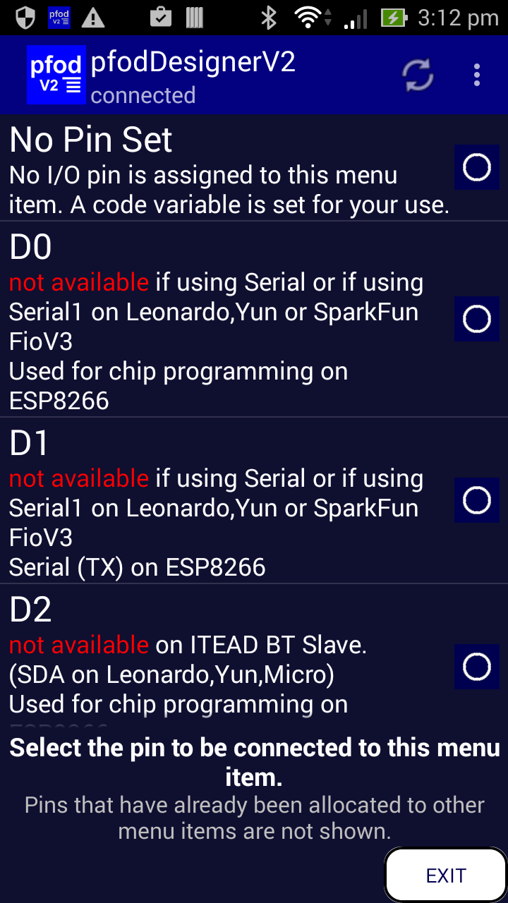
Scroll
down and select D13 from this list and the screen will close and re
display the Changing Menu Item
screen
with the updated pin.

You
can also change the initial state the output starts in when the power
is applied to the board or after the reset is pressed. Leave this
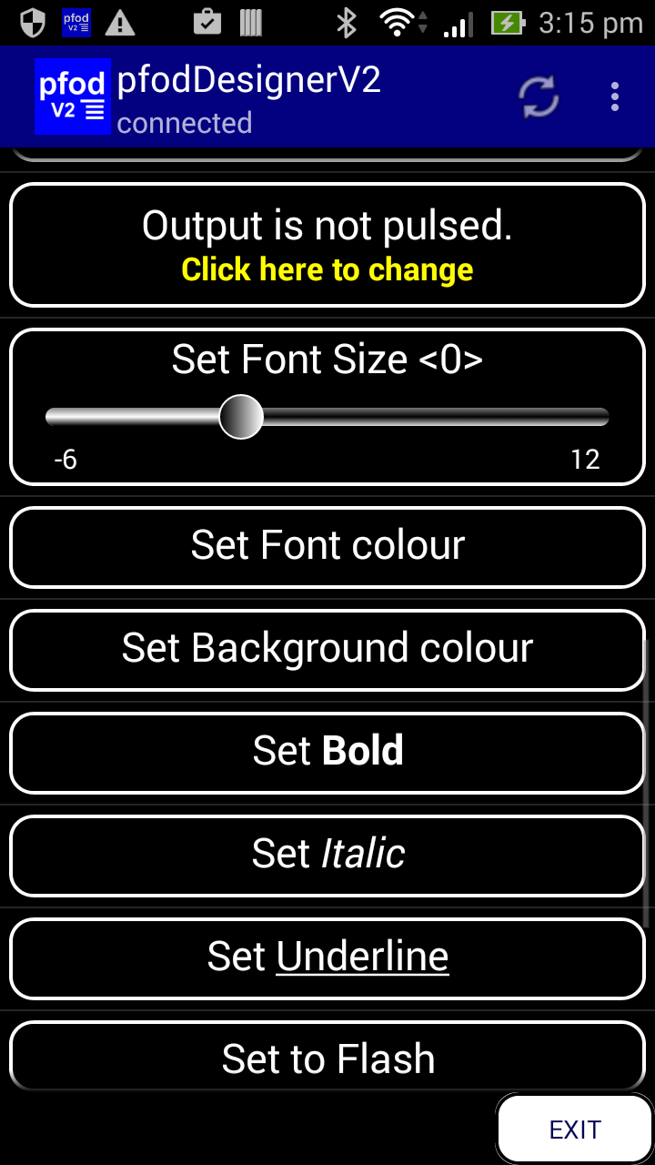
setting as Low for now. You also have the option to pulse the output
for a set time and then have return to its initial state. Click the
“Output is not pulsed” button to set a pulse width.
You can scroll down to see more options for changing this menu item.
Now
finish designing this menu item by editing the leading text to “Led
is ” and edit the Low text to “Off” and edit the
High text to “On”. Note the space at the end of “Led
is “. Set the font size to <+4> and the background to
Green.
Use
the mobile's back button to go back to the Editing
Menu screen and select Preview
Menu to see what the menu looks like
with this On/Off toggle slider.
If
you don't like the way it looks you can go back the Editing Menu_1
screen and edit the Menu or Prompt as you wish.
From the Editing Menu screen you can also delete un-needed buttons as well as changing the menu name. The menu name is for your use only. It is shown in the list of Existing Menus. It is not displayed to the user.
Now that you have finished the design you can click Generate Code to open the Generate Code Menu.
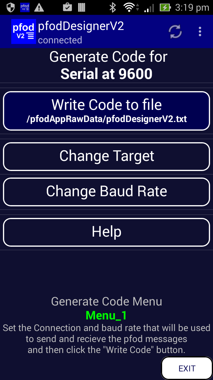
From
this menu you can change which sort of hardware you are using to
communicate with. When you select a serial connection you can also
set the what baud rate it will run at.
If you are doing the BLE tutorial, click on the “Using Serial” button to change the hardware.

Clicking
the Bluetooth Low Energy button gives you a choice of BLE devices.

Then
use the mobile's back button to go back to the Generate Code screen
and Click the Write Code to file
button to
generate the complete Arduino sketch.
For now, this
tutorial will complete by using the Serial selection at 9600 baud.
When you have set the serial and baud rate click the Write
Code to file button to generate
the complete Arduino sketch. This button writes the sketch to a file
on your mobile and displays the last 4k bytes in a screen.
You can exit pfodDesignerV2 now, your design has been
saved and is available under “Edit existing Menu”.
You
MUST exit the pfodDesignerV2 to ensure the last block of code is
written to the file.
Connect your mobile to your computer and turn on the USB Storage, or use a Wifi File Transfer App to access your mobile's storage from your computer. (See pfodAppForAndroidGettingStarted.pdf for more details) Note: pfodDesignerV2 cannot access the SD card to save the generated code while it is being accessed by the computer as USB Storage, so turn of USB Storage before running the pfodDesignerV2 again.
Navigate to /pfodAppRawData and open the pfodDesignerV2.txt in a text editor (such as WordPad). The pfodDesignerV2.txt file is over written to each time you click “Generate Code”.
Open
the Arduino IDE and make a new sketch, delete any code from the
sketch window and then copy and past the generated code into the
Arduino IDE.
A copy of the
generated code is here.
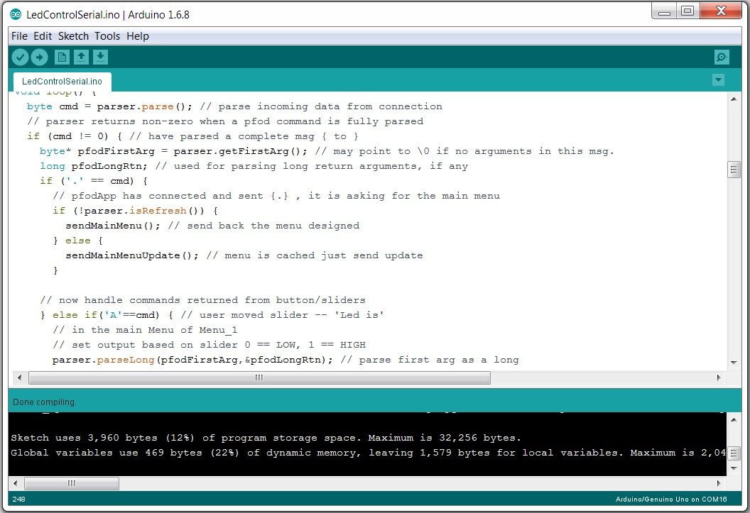
As
you can see, the code to generate this menu and handle the messages
from the mobile is quite small using only 12% of the Uno's program
space and 22% of it dynamic memory, leaving plenty of space for your
own code.
For Serial
connections, the generated code is a complete sketch which includes a
copy of the pfodParser
library code so you don't need to install any extra libraries.
All the code need to turn the Arduino output pins on and off when you
click the button in the pfodApp on your mobile is included in the
generated sketch.
Compile and Upload the sketch to your Uno board. Remember to remove the bluetooth shield first as it is connected the the same pins (D0 and D1) as the USB.
Set the switches on the Itead bluetooth shield. Set the 3.3V/5V switch to 5V and set the To FT232/To Board switch to To Board.
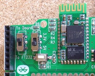
and
plug it into the Uno.
Install
pfodApp
from GooglePlay
and set up a Bluetooth connection to the itead Bluetooth shield, as
described in pfodAppForAndroidGettingStarted.pdf.
On connecting to the Uno + Bluetooth Shield, pfodApp will display your designed menu. Now as you click the On/Off toggle buttons on your mobile the leds will turn on and off.
This completes the tutorial. Bluetooth Low Energy (BLE) made simple with pfodApp uses this menu as an example of controlling various BLE shields. Simple Home Automation for Beginners looks at attaching relays, so that you can switch real things on and off.
But pfodApp can do much more than this. The pfod protocol is a rich but simple one and contains much more then just simple menus. Check out the full pfodSpecification.pdf for all the details and examples. Also see www.pfod.com.au for numerous example projects. All the screens used by the pfodDesignerV2 are standard pfod screens. The pfodDesignerV2 is just a pfodApp connected to a back-end that keeps track of your selections and serves up the requested screens. From the pfodDesignerV2 you can use the mobile's menu button to open the Debug View to see what pfod messages are being sent to generate the pfodDesignerV2 screens and what commands are sent back by your actions.
AndroidTM is a trademark of Google Inc. For use of the Arduino name see http://arduino.cc/en/Main/FAQ
The General Purpose Android/Arduino Control App.
pfodDevice™ and pfodApp™ are trade marks of Forward Computing and Control Pty. Ltd.

Contact Forward Computing and Control by
©Copyright 1996-2020 Forward Computing and Control Pty. Ltd.
ACN 003 669 994