
|
Home
| pfodApps/pfodDevices
| WebStringTemplates
| Java/J2EE
| Unix
| Torches
| Superannuation
| CRPS Treatment
|
| About
Us
|
|
|
BLE High Power Light Switch -- 2023
|
by Matthew Ford 30th
March 2024 (original 5th May 2023)
©
Forward Computing and Control Pty. Ltd. NSW Australia
All rights
reserved.


Update 30th March 2024 –
Revised
circuit and code to Rev 15 to fix hallway operation and flicker. 5W
Led lamps need to be dimmable to be controlled.
Note: The
GT823E-01 module used here seems to be in short supply. The
HOLYIOT-YJ-16048-NRF52832
is
a suitable alternative, but needs the PCB to modified to suit.
Update
25th May 2023 – For
most installations use the BLE
Led Light Switch – 2023 which can control upto 200W. For
higher wattages and for hallway switches use this project. This
project and BLE
Led Light Switch – 2023 supersedes
these previous BLE light switch projects:-, Remote
Controlled Light Switch – 2017, BLE
Power Control with pfodApp
This page covers retrofitting BLE (Bluetooth
Low Energy) control to an existing light switch. This project can
handle load in the range of 5W to >1000W.
No
extra wiring is required, just add the BLE control circuit to the
existing switch.
The power is
remotely switch from your Android Mobile via pfodApp
or Nordic nRF Toolbox.
– Costs about the same as a remote
controlled light and much less expensive for multiple lights on the
same switch.
– Remote still works when the light is switched
off at the wall switch. Existing light switches continue to work as a
manual on/off override.
– Simple to install behind an
existing light switch.
– Works with switches at each end of
a hallway.
– No separate power supply required.
–
No additional wiring required. No need to add a Neutral wire, just
connect the controller in place of the light switch.
– 98%
to 99.8% efficiency when light is on and less than 90mW (<400uA)
when light is off.
– 110VAC / 240VAC versions can control 5W
to >1kW of resistive load (~100W of incandescent lamps, see Inrush
Current below)
– The top half of the PCB can be trimmed off
to allow for easier mounting behind slim line light switches.
–
Very low off current, <400uA, means Led lamps do not flash when
switched Off.
– If the circuit fails the existing light
switch continues to operate as normal.
– Optional additional
functions such as light off after set time (see below) or control
from remote sensor.
The project has been developed over the last 7
years. The first version, Remote
Controlled Light Switch – 2017, used the idea of having a
Zener in series with the load to supply the voltage to run the BLE
module and a bypass resistor to keep a small amount of current
flowing to power the BLE module when the switch was off. This worked
well but had the following limitations:-
a) the 'off' current of
a few mA caused non-dimmable LED light to flash,
b) the load that
could be controlled was limited by the Zener power handing
capabilities, ~120W/240VAC at 25degC, less at higher ambient
temperatures.
The second version, BLE Power Control with pfodApp, extended the power handling to >1kW by using a current transformer to power the BLE module. This version was time consuming to build, bulky and at high loads supplied excess current to the BLE module which had to be dissipated as heat.
The
third version, BLE
Led Light Switch – 2023, revised the Remote
Controlled Light Switch – 2017 to extend the power handling
by bypassing the Zener most of the time and reduced the off current
to uA's by revising the software and using low leakage ceramic supply
capacitors. It also used the latest high voltage nFets, that are
normally on with zero gate volts, instead of a relay. This version
worked well with the following limitations:-
a) the load that
could be controlled was limited by the full wave rectifier current
carrying capacity,
b) two way hallway switches could not be
accommodated,
c) if the circuit fails the manual over light
switch does not work either.
In spite of those limitations, BLE Led Light Switch – 2023, is recommended for controlling modern LED lights via BLE
This High Power version is only recommended if you need to control a hallway light, that has two switches OR you need to control more than 200W of Leds or 100W of incandescent lamps. This High Power version uses a change over relay that supports remote control of two way hallway switches while maintaining manual override via the existing wall switches even if the circuit fails. This version also uses currently available BLE modules and programmers. (but see notes below)
For all the hype about Home Automation, current remote control lighting solutions require either:- rewiring to provide a supply power for the control or need continual battery replacement or they stop working when the existing light switch is turned off. This project avoids all those limitations.
This project supersedes these previous projects:- Remote Controlled Light Switch – Retrofit – 2017 and Retrofit BLE Control to an Existing Load of 10W to >1000W – 2017 and uses currently available BLE modules and programmers and has a revised circuit that improves efficiency when the light is On and reduces the quiescent current when the light is Off.
This solution is Mains Powered but DOES NOT require any extra wiring to be installed. Just install the BLE PCB inside the existing light switch using the existing two wires (the Active and the wire back to the light bulb). This solution is Mains Powered and does not to use batteries. A battery powered remote would need an accessible battery case for user replacement, so you could not just add the remote behind the existing light switch. Having a Mains Powered remote avoids these problems.
The existing light switch is retained and continues to work. That is you can continue to turn the light on and off from the wall switch as well as being able to turn it on and off from your Android mobile. In particular you can remotely turn the light ON after you used the wall switch to turn it OFF.
Commercial remote controlled light bulbs plug into the existing light socket BUT the wall switch needs to be ON in order to use the remote. If the wall switch if OFF you cannot use the remote to switch the light ON. The circuit used here continues to work when the light is switched OFF at the wall.
Once you have a microprocessor controlling your light, you can readily add additional functions. Such as turning the light off after a given time or controlling the light via a remote sensor.
Auto-turn OFF
This code supports auto-turn
off with manual override. If you set a non-zero ms value for
OFF_TIME_ms , the lamp will
automatically turn off after that time. You can manually disable the
auto-turn off after you turn the lamp on by turning the lamp off and
then on within 3 seconds. This will disable the auto-turn off until
the next time the lamp is turned on.
Here is the standard light switch wiring.

The wall switch disconnects the mains (110VAC
/ 240VAC) active wire from the light.
The idea for this BLE control dates back, a number of years, to a simple constant current source circuit. (National Semiconductor Application Note 103, Figure 5, George Cleveland, August 1980)
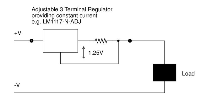
What is interesting about this circuit is that it only has two wires, one and one out. There is no connection to the -ve supply (gnd) except through the load. This circuit pulls itself up by its boot straps. It uses the voltage drop across the regulator and resistor to power the regulator.
This project uses a similar idea.
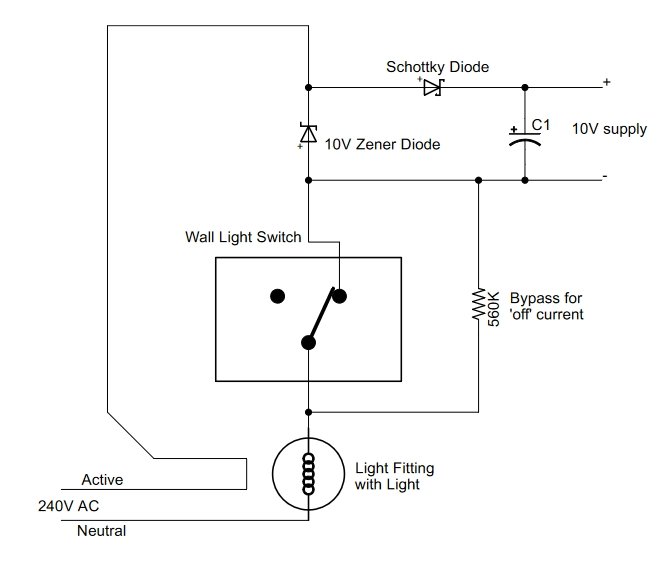
In this circuit, when the Wall Switch is OFF, the
560K resistor, bypasses the wall switch to supply a small amount of
current to keep the BLE circuit running. This basic BLE power supply
circuit has two limitations,
i) all the load current flows
through the Zener when the wall switch is on and
ii) when the
wall switch is off the supply capacitor is only charged by the
positive half cycles of the AC main.
This revised circuit solves those problems.

The nFET, U1, shorts out the Zener, Z$1, most of the time when the lamp is ON and is only turned off when the BLE module detects that the supply capacitor, C1, needs topping up. The second, low wattage, Zener diode, Z$2, in series with the bypass resistor, charges C1 on the second half cycle of the AC mains when the Wall Switch if Off.
Below is the schematic for the BLE High Power Lights R15. (A pdf version is here.) The parts list is BLE_Lights_R15_PartsList.csv.
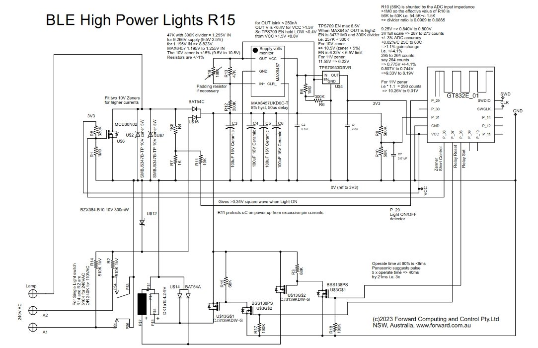
The MAX6457 supply monitor is used to delay the startup of the BLE module until C1-C4 (400uF) have charged up to ~9.5V and can supply the 20mA or so of start-up current the BLE module needs.
The 3v3 supply from the TPS709 turns the U$6 FET on as soon as the MAX6457 supply monitor releases its enable. The U$6 FET bypasses the 10V 5W Zener diode(s) for the 500ms between when the BLE module is powered up and when it start running the sketch setup() / loop() code. The avoids burning out the the 5W 10V Zener carrying 8A (=>800W) if the light is on when the mains power is applied.
The voltage on the supply capacitors, C1 to C4, is monitored by a BLE module ADC input via the R10/R9 divider. When the voltage drops below about 7.5V, the bypass FET, U$6, is turned off for a short time to let the 10V 5W Zener recharge the capacitors.
The dual P-FETs, CJ3139KDW-G drive the positive leads of 9V latching relay coils. The dual N-FETs, BSS138PS, provide the level shifting between the 3V3 BLE module outputs and the 10V gate drive of the P-FETs
The light ON detection circuit is R4, R7. This
circuit outputs >3.4 when the light is ON and load current is
flowing through the high power 10V Zener, U$2 / U$7. This drives an
input to an lp_comparitor to detect when 5W Zener is carrying load
current. The 10K resistor, R11, protects the BLE module's input, from
excessive current due to this over-voltage input. When the lamp if
OFF, R4, R7 = 2.8K limits the voltage across the 5W Zener of <2V
when passing the 400uA off current.
The light ON detection circuit
is also used to display the current state on the remote control app
when the wall switch has been used to manual turn the light
On/Off.
This light ON detection circuit was re-designed from
earlier versions which looked at the voltage across the low power
Zener, U$12 to see when the light was off. However in a hallway
installation the induced hum in the wires running between the hallway
switches caused enough current to flow in U$12 to trigger the off
detector.
When the circuit is first powered up, or after a mains interruption, the Set/Reset state if the latching relay is unknown. The software recognizes this and goes through a synchronizing sequence to align the relay state with the software state.
See the code comments for more details of the operation.
WARNING:
This project is for Experienced Constructors Only. The board is Mains
Powered and can be deadly if any part of it is touched while it is
running. The wiring of this board into the existing light switch
circuit should only be done by a qualified Electrician.
See
below for how to safely test the circuit using low voltages.
Below is the wiring diagram for connecting the BLE High Power Remote Control Light Switch to the existing Wall Switch so that both the wall switch and the BLE remote control can operate the light. A pdf version is here.

Wall light switches in Australia all come as SPDT (change over) switches so that they can be used as hallway light switches. In the wiring diagram above the existing Wall Light Switch is wired as a hallway switch to the BLE Light Controller that is mounted in the behind the Light Switch.
In the state shown above the ceiling light is OFF and the bottom resistor is supplying power to the BLE controller. If you manually switch the wall switch then power flows through the latch relay contact and turns the ceiling light ON. On the other hand if you leave the wall switch as it was and remotely trigger the latching relay to change over it will now connect the power from the wall switch to turn the light ON.
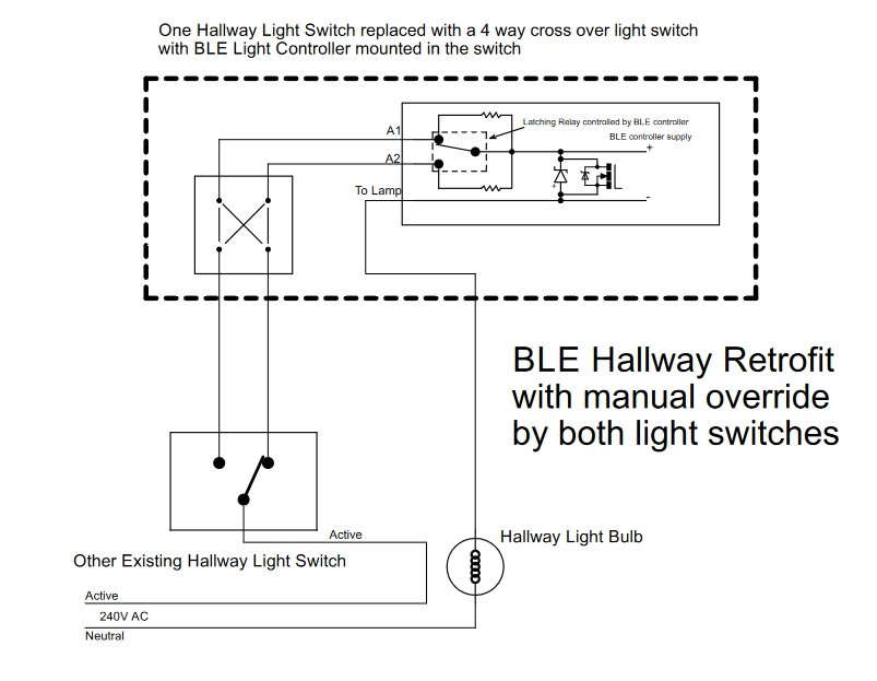
If you retro-fitting the BLE Remote Control Light Switch to one end of an existing pair of hallway switches, you will need to replace that switch with and 'intermediate' or 4 way crossover switch. (That is the same type of switch that you would use if you were adding a third switch to you existing two hallway switches.)
Below is the wiring for retro-fitting a hallway light switch with BLE Remote Control. (A pdf version is here)
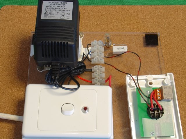
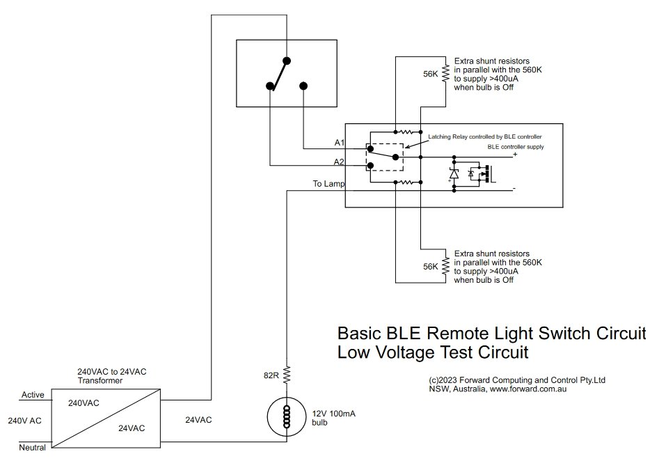
To safely test the BLE Remote Light Switch, use a 24VAC supply instead of the mains and replace the light with a 12V 100mA bulb and an 82ohm 5W resistor. You will also need to temporarily add 56K resistors across the R12 and R2, so that the Off current is still >400uA. With this low voltage set up you can use a grounded oscilloscope to check the circuits operation. Once you have tested the circuit, remove the 56K resistors and wire the PCB in behind the light switch.
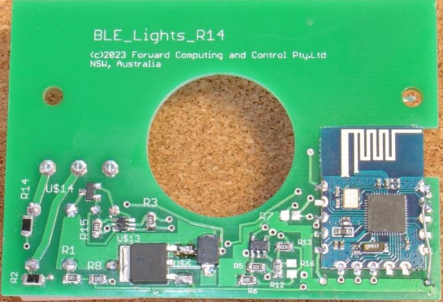
I used Eagle Cad to layout the PCB. I supplied a zip of the Gerber files to www.pcbcart.com for the manufacture using 2oz copper. I used gerbv to view and check the Gerber files before submitting for manufacture.
The latest PCB is Rev BLE_Lights_14A and includes a few minor corrections. The Eagle Cad files are here. The PCB Gerber files are here. The parts list (.csv) is here.
The bypass FET used here can only handle about 4A (~1000W / 240VAC) with the heat sinking provided by this board layout.
The circuit board is laid out for a GT823E-01 nRF52832 module, but the PCB can be modified to accommodate other small modules. See Easy Very Low Power BLE in Arduino – 2022 for some alternative modules. Easy Very Low Power BLE in Arduino – 2022 also covers how to program the nRF52832 module.
Note: The GT823E-01 module seems to be in short supply. The HOLYIOT-YJ-16048-NRF52832 is a suitable alternative, but needs the PCB to modified to suit.
The nRF52832 was programmed with the BLE_LightSwitch_R15.ino sketch. That sketch will serve up a control menu for pfodApp, but you can also use Nordic nRF Toolbox to send the commands to turn the light on, {A} or off {B} or toggle on/off {T} . See Very Simple BLE Power Switch for more an example of using the Nordic nRF Toolbox.
Once the board is programmed you can connect to is using pfodApp. Set up a connection to the BLE Light Switch as described in pfodAppForAndroidGettingStarted.pdf, then when pfodApp connects, your Android mobile will display the following button menu and the current state of the light.

This section covers some of design considerations and calculations. First some formulas for converting between RMS and Average Current.
The RMS value of the main sine wave is used to
calculate the rms current for a given Wattage in a resistor (e.g. an
lamp). A 60W lamp will draw 0.25A RMS from a 240V RMS main supply.
(But see below for inrush current)
The Peak value is the maximum
value of the sine wave. For 240V RMS, the peak voltage is sqrt(2) *
240 = 1.414*240 = 339V. For 0.25A RMS the peak current is
0.35A.
The Average value is used in DC and
rectified circuits (like this one). It is the average over the
rectified sine wave. For 1A RMS the average rectified current = Peak
Current * 2 / pi = 1.414*1*2/3.142 = 0.9Aavg
The >99.8% efficiency when ON may look unbelievable, but is necessary if the circuit is not to go up in smoke. For an 8A load at 240VAC the load wattage is 1.92kW. The >99.8% efficiency means that less than 0.2% of the power is dissipated in the circuit. That is less than 0.2% x 1.92kW = 3.84W. The relay has an contact resistance of ~30mOhms => 1.92W loss in the contact. The nFET that shorts the Zener most of the time has an maximum on resistance of <9mOhms => 0.58W (plus some switching losses). The Zener is turned on for <40us each 3ms, for high loads. That is it is turned on <1.3% of the time. For 8A RMS the average current is 7.2A. If the Zener was on all the time, half the time this current would flow through the Zener in the reverse direction, i.e. 10V and the other half of the time in the forward direction, i.e. <1.2V This gives 7.2A x 10V / 2 + 7.2A x 1.2V / 2 = 56W is on full time. For 1.3% duty cycle => 0.73W. Adding these three losses together gives ~3.2W or <0.2% of the 1.92kW load.
For a 5W/240VAC lamp, the RMS current is 21mA RMS. (18.75mA avg). This gives a relay contact loss of 26uW. A NFET loss of 8uW and Zener loss of 105mW for a total of 0.1W or 2% loss. That is ~98% efficiency for a 5W/240VAC load.
When power is first applied to the circuit, it takes about 500ms before the BLE module starts running the main code and can pull the gate of nFET, U1, high to short out the Zener. With an 8A load the Zener would burn out in this time. To avoid that, the gate of U1 is pulled high by the 3V3 supply and so bypasses the Zener as soon as the power is applied. The BLE module then overrides this pullup to control the Zener on/off. As well as this the capacitors need to charge up to ~9.5V before the 3V3 supply is enabled to turn on the N-FET. Allowing less than mains cycle to that, then from Fig 5 of the SMBJ5342B-TP datasheet, the Zener can withstand ~8A on startup.
When the load is off, the main 5W Zener is turned ON so that if whent lamp is turned on, either by the BLE or the wall switch, lamp ON detection circuit will trigger on the first AC pulse. When the lamp is switch off, a missing pulse detector is used to detect the absence of the AC waveform through the 5W Zener.
The resistance of incandescent lamps (the old filament bulbs) is much low when the lamp is cold (off) and rises as the filament heats up and the lamp starts to shine. This initial low resistance results in a turn on current of some 15 times the lamp's running current. That is a 100W/240VAC incandescent lamp can draw some 6.25A RMS on turn on. A 100W/110VAC can draw some 13.6A RMS. This initial inrush current drops back to the running current over about 0.1sec. There are two points to consider here:- the relay contact rating and the startup Zener surge rating. A second parallel Zener can added to enhance the surge rating, but continual switching of the relay above it contact rating will shorten its life.
One solution is to add NTC Inrush Current Limiter. This device starts out with a high resistance which reduces as it is heated up by the load current. While effective, the downside of these devices is that they are inefficient and add some 20% loss to the circuit. Electric heater elements have a negligible inrush current as resistance of nichorme wire only changes by about 7% for 1000degC change in its temperature. Led lights do not have the problems of incandescent lamps inrush current, but may still exhibit some smaller inrush current as their supply capacitors, if any, charge up.
For most installations use the BLE Led Light Switch – 2023 which can control upto 200W. For higher wattages and for hallway switches use this project. This project and BLE Led Light Switch – 2023 supersedes these previous BLE light switch projects:-, Remote Controlled Light Switch – 2017, BLE Power Control with pfodApp
This project can control loads from 5W to >1kW with efficiencies of 98% to 99.8% and allows remote control via BLE while maintaining the existing switch as a manual override. The BLE remote control can turn the lights back on even if the manual switch has turned them off. The code has an option for auto-turn off after a fixed time.
If the remote control circuit should fail, or you cannot find your mobile, the manual override switch continues to work. The cost of this project is about the same a single BLE light bulb, but much cheaper if you have multiple light bulbs on a single wall switch.
AndroidTM is a trademark of Google Inc. For use of the Arduino name see http://arduino.cc/en/Main/FAQ
The General Purpose Android/Arduino Control App.
pfodDevice™ and pfodApp™ are trade marks of Forward Computing and Control Pty. Ltd.

Contact Forward Computing and Control by
©Copyright 1996-2024 Forward Computing and Control Pty. Ltd.
ACN 003 669 994