
|
Home
| pfodApps/pfodDevices
| WebStringTemplates
| Java/J2EE
| Unix
| Torches
| Superannuation
|
| About
Us
|

|
BLE Power Control with pfodApp
|
by Matthew Ford 16th May 2023 (original
22nd November 2017)
© Forward Computing and
Control Pty. Ltd. NSW Australia
All rights reserved.
Update 16th May 2023 -- This has been superseded by BLE High Power Light Switch, 2023 -- Retrofit, which does not need the current transformer.
Update 12th March 2023 -- This instructable has been superseded by BLE LED Light Switch, 2023 -- Retrofit, which handles ~200W and uses currently available BLE modules and programmers and does not require winding a current transformer
Update: 13th July 2018 - added 3-terminal regulator
This page covers BLE (Bluetooth Low Energy)
control of an existing load in the range 10W to >1000W. The power
is remotely switch from your Android Mobile via pfodApp.
No extra wiring is required, just
add the BLE control circuit to the existing switch.
Often
when retrofitting home automation to existing installations, the only
reasonable place to add the control is at the existing switch.
Particularly when you want to keep the switch as a manual override.
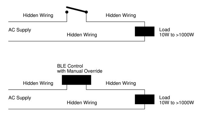
However usually there are only two wires at the switch, the Active
and the switch wire to the load, no Neutral. As shown above this BLE
control works with just those two wires and includes a manual
override switch. Both the Remote control and the manual switch work
when the load is On or Off.
The particular example here is for controlling a 240W bank of lights by placing the circuit behind the wall switch. Code is provided for both RedBear BLE Nano (V1.5) and RedBear BLE Nano V2 to display the control button on pfodApp. An optional timed Auto Off function is also available in the code.
WARNING: This project is for Experienced Constructors Only. The board is Mains Powered and can be deadly if any part of it is touched while it is running. The wiring of this board into the existing light switch circuit should only be done by a qualified Electrician.
The previous project, Retrofit an Existing Light Switch with Remote Control, worked will for loads between 10W and 120W for 240VAC (or 5W to 60W for 110VAC) but was not able to cope with lounge room lights that consist of 10 x 20W = 200W of compact fluorescents. This project adds a few components and a hand wound toroid to remove that load limitation while retaining all the advantages of the previous project. The load this design can switch is only limited by the relay contact ratings. The relay used here can switch 16 Amps resistive. That is >1500W at 110VAC and >3500W at 240VAC. The BLE control circuit and relay uses mWs and so it does not even get warm.
The advantages of this project are:-
(see
Retrofit an
Existing Light Switch with Remote Control for more details)
This solution is Mains Powered but DOES NOT require any extra wiring to be installed. Just install add the control circuit to the existing manual switch.
The manual override switch continues to control the load even if the remote control circuit fails (or you cannot find your mobile). Also you can remotely turn the load ON after you have used the manual override switch to turn it OFF
Once you have a microprocessor controlling your load, you can readily add additional functions. The code in this project includes an option to turn the load off after a given time. You could also add a temperature sensor to control the load and remotely adjust the temperature setpoint.
This diagram is from the Bluetooth V5 “Mesh Profile Specification 1.0”, July 13 th , 2017, Bluetooth SIG
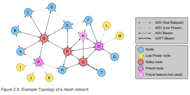
As you can see it consists of a number Relay nodes in a mesh. The Relay nodes are active all the time and provide access to other nodes in the mesh and to the battery powered sensors. Installing this Mains Powered BLE Remote module will automatically provide a set of nodes across your house that can be added to the mesh as Relay nodes. RedBear BLE Nano V2 is Bluetooth V5 compatible.
However the BLE Mesh specification is very recent and there are currently no example implementations. So setting up the mesh is not covered in this project but once example code becomes available you will be able to re-program you RedBear BLE Nano V2 to provide a meshed Home Automation Network
The idea for this control dates back, a number of years, to a simple constant current source circuit. (National Semiconductor Application Note 103, Figure 5, George Cleveland, August 1980)
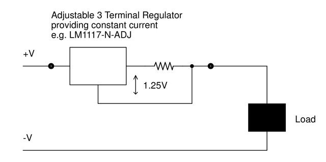
What is interesting about this circuit is that it only has two wires, one and one out. There is no connection to the -ve supply (gnd) except through the load. This circuit pulls itself up by its boot straps. It uses the voltage drop across the regulator and resistor to power the regulator.
The Retrofit an Existing Light Switch with Remote Control used a similar idea.
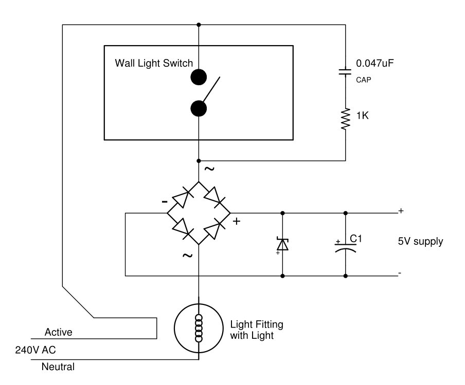
A 5V6 Zener in series with the load supply the power for the BLE controller and the latching relay. When the load is turned OFF a very small amount of current less then 5mA is continues to flow though the zener (and the load) via the 0.047uF and 1K bypassing the open switch. This tiny current, which is barely detectable and 'safe', is sufficient to power the BLE controller when the load is off and also charge up a capacitor to drive the latching relay to switch the load on remotely. See Retrofit an Existing Light Switch with Remote Control for the full circuit and details.
The limitation of the above circuit is that when the load is ON, all the load current passes through the zener. Using a 5W zener limits the current to about half an amp. That is for a 60W lamp (at 110VAC) 3W is being dissipated as heat from the zener when the load is ON. For 110V AC systems this limits the load to about 60W, and for for 240V systems about 120W. With modern LED lighting this often sufficient, however it would not cope with the 200W of lamps in the lounge room.
The circuit described here removes that limitation and allows kilowatts of power to be controlled remotely by mWs via BLE and pfodApp.
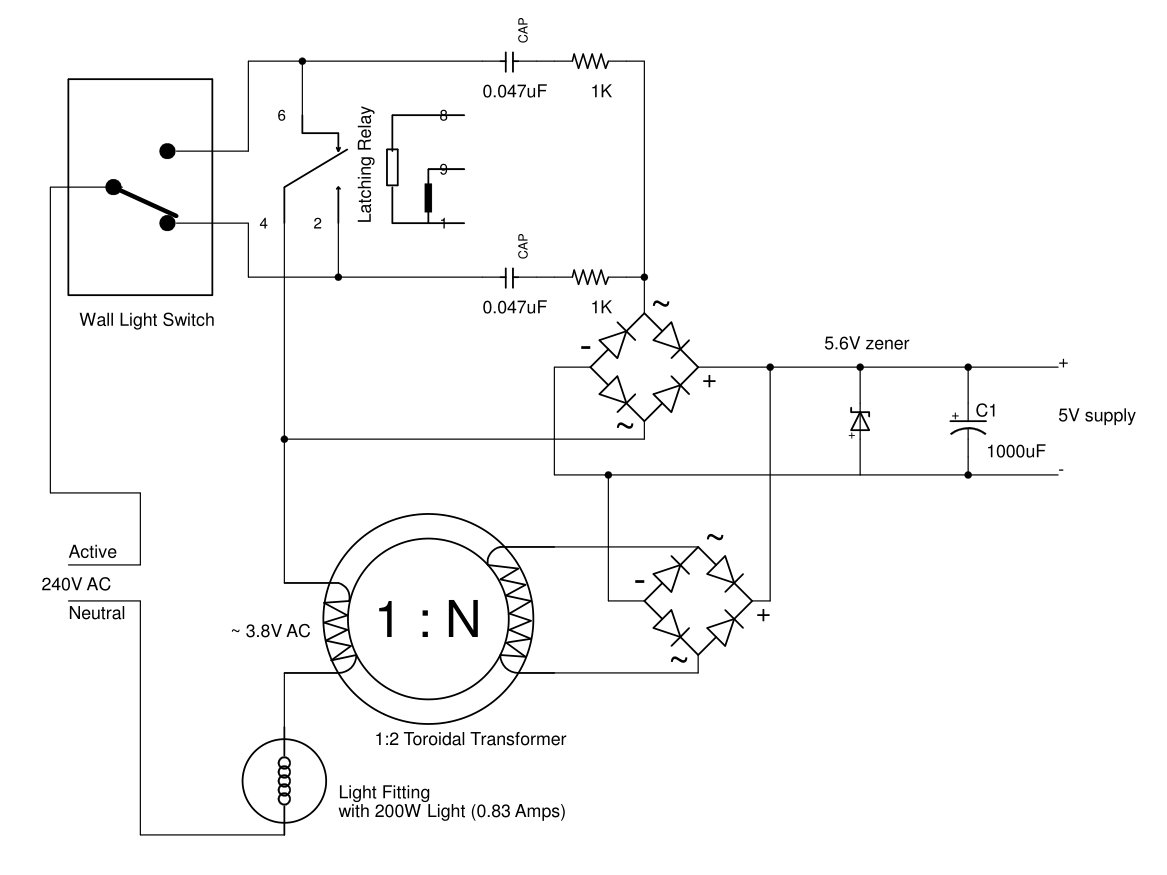
The circuit above shows the load OFF. In this state the BLE controller is supplied via the 0.047uF and 1K as in the previous circuit. When the load is ON (i.e. operate either the wall switch or latching relay in the above circuit), the top bridge rectifier and the 0.047uF and 1K components are shorted out by the relay and switch. The full load current then flows through the Toroidal Transformer which supplies the mWs needed for the control circuit. Although the toroid is shown as having about 3.8V AC across it primary, the primary winding is almost entirely reactive and out of phase with the load voltage so very little power is actually taken by the toroid, mWs actually.
The complete circuit diagram is here (pdf). The parts list, BLE_HighPower_Controller_Parts.csv, is here
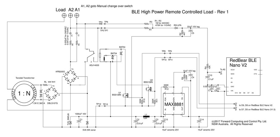
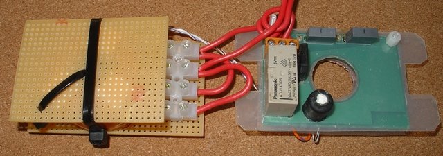
You can see the additional components on the left hand side. The toroidal transformer, surge suppressor, limiting resistor and full wave rectifier. Retrofit an Existing Light Switch with Remote Control describes the rest of the circuit.
The voltage supplied by the Toroidal Transformer varies with the load current (see below for more details). More the 7V is needed to drive the full wave rectifier and the zener. The RL resistor is chosen to limit the current through the Zener to a few mA's, say less than 20mA. Having a Toroidal supply voltage that varies with load current is not much of a problem because of the wide range of currents the zener can handle, 0.1mA to 900mA, which gives a wide range available voltage drops across RL and hence a wide range of acceptable Toroidal supply voltages. Of course for efficiency we would like the output voltage from the toroid to more closely match what is needed.
On checking the hardware after a few months, the current limiting resistor RL looked slightly burned, so the toroidal transformer circuit was modified (modifiedCircuit.pdf) to use a 3-terminal current limiter instead.
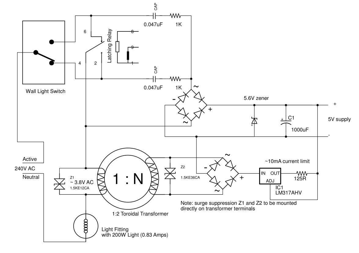
Z1 (a bi-directional zener) was added to limit the voltage spike on the primary to <12V and IC1 as added to limit the current supplied by the secondary to ~10mA. An LM318AHV with an input voltage limit of 60V was used and Z2 limits the transformer output to <36V to protect the LM318AHV.
A toroidal transformer is used here because it has very low magnetic flux leakage and so minimizes the interference with the rest of the circuit. There are two main types of toroid cores, iron powder and ferrite. For this design you need to use the iron powder type which is designed for power used. I used a HY-2 core from Jaycar, LO-1246. 14.8mm Height, 40.6mm OD, 23.6mm ID. Here is specification sheet. That sheet notes that T14, T27 and T40 toroids are similar so you could try one of those instead.
Transformer design is something of an art due to the non-linear nature of the B-H curve, the magnetic hysteresis and the core and wire losses. Magnetic Inc has a design process that seems to be straight forward, but requires Excel and does not run under Open Office, so I did not use it. Luckily here you only need to get the design roughly right and you can adjust it by adding primary turns or increasing RL. I used the design process below and got an acceptable transformer first time, after adding a second primary winding. I refined the number of turns and the winding process for the second transformer.
Basic design criteria are :-
There needs to be enough change in magnetic field (H) in the core to overcome the B-H curve hysteresis, but not enough to saturate the core. i.e. say 4500 to 12000 Gauss.
Primary Volts depends on:- the inductance of the primary winding and the mains frequency to give the reactance and then times by the load current to give the primary winding's voltage.
The secondary volts depends, roughly, on the turns ratio secondary to primary time the primary volts. Core losses and winding resistance mean the output is always less than an ideal transformer.
The secondary volts need to exceed 6.8V ( == 5.6V (zener) + 2 * 0.6V (rectifier diodes) ) for enough of the AC cycle to provide an average current through the zener greater then a few mA to power the BLE circuit.
The primary winding wire size needs to be chose to be able to carry the full load current. The secondary will normally only be carrying mA after inserting the RL limiting resistor so the secondary winding wire size is not critical.
The Toroid Inductance per Turn Calculator will calculate the inductance and Gauss/Amp for a given number of turns, given the toroid dimensions and permeability, ui.
For this application, the lounge room lights, the load current is about 0.9A. Assuming a 2 : 1 step up transformer and greater than 6.8V peak on the secondary then the peak primary voltage needs to be greater than 6.8 /2 = 3.4V Peak / sqrt(2) == AC RMS volts so the primary RMS volts needs to be greater then 3.4 / 1.414 = 2.4V RMS. So lets aim for a primary RMS volts of say about 3V AC.
The primary voltage depends on the reactance times the load current i.e. 3/0.9 = 3.33 primary reactance. The reactance for winding is give by 2 * pi * f * L, where f is the frequency and L is the inductance. So for a 50Hz main system L = 3.33 / (2 * pi * 50) == 0.01 H == 10000 uH
Using the Toroid Inductance per Turn Calculator and inserting the toroid dimensions of 14.8mm Height, 40.6mm OD, 23.6mm ID, and assuming 150 for ui gives for 200 turns 9635uH and 3820 Gauss/A Note: the ui is listed in the specification as 75 but for the lower levels of flux density used here, 150 is closer to the correct figure. This was determined by measuring the final coil's primary voltage. But don't worry to much about the exact figure as you can fix the primary winding later.
So using 200 turns give, for a 50Hz, f, supply the reactance == 2*pi*f*L == 2 * 3.142 * 50 * 9635e-6 = 3.03 and so the volts across the primary winding at 0.9A RMS AC is 3.03 * 0.9 = 2.72V RMS for a peak voltage of 3.85V and a secondary peak voltage of 7.7V, assuming a 2 : 1 step up transformer.
The peak Gauss is 3820 Gauss / A * 0.9A == 4861 Gauss which is less then the 12000 Gauss saturation level for this core.
For a 2:1 transformer the secondary winding needs to have 400 turns. Testing showed that this design worked and a RL limiting resistor of 150 ohms gave a mean zener current of approximately 6mA.
The primary wire size was calculated using Calculating mains frequency power transformers – Choosing the right wire. For 0.9A that web page gave 0.677 mm dia. So 0.63mm dia enamelled wire (Jaycar WW-4018) was used for the primary and 0.25mm dia enamelled wire (Jaycar WW-4012) was used for the secondary.
The
actual transformer construction used a single secondary winding of
400 turns of 0.25mm dia enamelled wire and two (2) primary windings
of 200 turns each of 0.63mm dia enamelled wire. This configuration
enables the transformer to be configured to work with load currents
in the range 0.3A to 2A i.e. (33W to 220W at 110V OR 72W to 480W at
240V).
Connecting the primary windings is series, doubles the
inductance and allows the transformer to be used for currents as low
as 0.3A (33W at 110V or 72W at 240V) with RL == 3R3 and up to 0.9A
with RL = 150 ohms.
Connecting the two primary windings in
parallel double their current carrying capacity and provides for load
current of 0.9A to 2A (220W at 110V and 480W at 240V) with an
appropriate RL.
For my application controlling 200W of lights at 240V, I connected the winding is parallel and used 47 ohms for RL. This closely match the output voltage to what was needed while allowing the circuit to still function for loads down to 150W if one or more bulbs failed.
At 60 Hz the reactance is 20% higher so you don't need as many turns. Since the inductance varies as N^2 (turns squared) where N is the number of turns. For 60Hz systems you can reduce the number of turns by about 9%. That is 365 turns for the secondary and 183 turns for each primary to cover 0.3A to 2A as described above.
The relay used in this project can switch a resistive load current of up to 16A. The design above will work for 0.3A to 2A. Above that the toroid starts to saturate and the primary winding wire size is not large enough to carry the load current. The result, confirmed by testing with an 8.5A load, is a stinking hot transformer.
As an example of a high load design, let's design for a 10A load in a 60Hz 110V system. That is 1100W at 110V.
Assume a primary voltage of say 3.5V RMS and a 2 : 1 transformer allowing for some losses, then the primary reactance needed is 3.5V / 10A = 0.35. For 60Hz this implies an inductance of 0.35/( 2*pi * 60) = 928.4 uH
Using ui of 75 this time, as the flux density will be higher, see below, a few trials of the number of turns in Toroid Inductance per Turn Calculator gives 88 turns for the primary and 842 Gauss / A for the flux density or 8420 Gauss at 10A which is still within the 12000 Gauss saturation limit. At this level of flux the ui is probably still higher then 75 but you can adjust the number of primary turns when you test the transformer below.
Calculating mains frequency power transformers gives a wire size of 4mm^2 cross section or 2.25mm dia or perhaps a bit less say two primary windings of 88 turns each of 2mm^2 cross section i.e. 1.6mm dia wire, connected in parallel to give a total of 4mm^2 cross section.
To construct and test this design, wind a 176 turn secondary winding (to give twice the output voltage as before) and then wind just one 88 turn primary of 1.6mm dia wire. Note: Leave extra wire on the former so you can add more turns if needed. Then connect the 10A load and see if the secondary can supply the voltage/current required to run the BLE circuit. The 1.6mm dia wire can withstand the 10A for the short time you are measuring secondary.
If there are sufficient volts, determine the RL necessary to limit the current, and perhaps take off a few turns if there is a lot of excess voltage. Otherwise if there is not enough secondary voltage, add some more turns to the primary to increase the primary voltage and hence the secondary voltage. The primary voltage increase as N^2 while the secondary voltage decreases as roughly 1/N due the change in the turns ratio, so adding primary windings will increase the secondary voltage.
Once you have determined the number of primary turns you need, you can then wind the second primary winding to parallel with the first one to provide the full load current carrying capacity.
To wind the transformer you first need to wind the wire on to a former that will fit through the toroid.
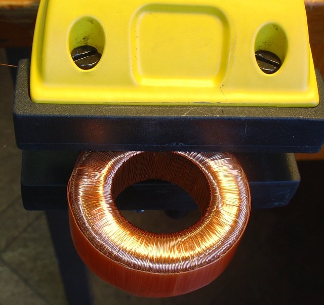
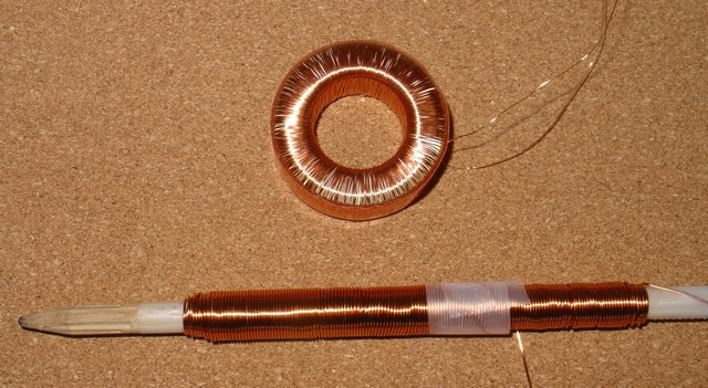
First calculate how much wire you need. For the Jaycar, LO-1246 toroid each turn is about 2 x 14.8 + 2 * (40.6 – 23.6)/2 == 46.6mm. So for 400 turns you need about 18.64m of wire.
Next calculate the size of single turn on the former you will use. I used a pencil about 7.1mm dia which gave a turn length of pi*d = 3.14 * 7.1 == 22.8mm per turn. So for 18.6m of wire I needed about 840 turns on the former. Rather than count the turns being would onto the former, I calculated the approximate length of 840 turns, assuming 0.26mm dia wire (a bit larger then the actual 0.25mm dia of the wire). 0.26 * 840 = 220mm long winding of close wound turns to get 18.6m of wire on to the former. Since the pencil was only 140mm long I would need atleast 2.2 layers of 100mm length each. Finally I added about 20% extra wire to allow for sloppy winding and increased turn length on the toroid for the second layer and actually put 3 layers of 100mm long each on the pencil former.
To wind the wire onto the pencil former I used a very slow speed drill press to rotate the pencil. Using length of the layers as the guide, I did not need to count turns. You could also use a hand drill mounted in a vice.
Holding the toroid in a soft jaw vice that could rotate the jaws to hold the toroid horizontal, I wound the secondary winding first. Starting with a layer of thin double sided tape around the outside of the toroid to help keep the wire in place as I wound it. I added another layer of tap between each layer to help keep things in place. You can see the final layer of tap in the photo above. I purchased the vice specially for this job, a Stanley Multi Angle Hobby Vice. It was well worth the money.
A similar calculation was done to prepare the winding former for the two primary windings. Although is that case I measured the new size of the toroid, with the secondary winding in place, to calculate the turn length. Above is a photo of the transformer with the secondary wound and the wire for first primary winding on the former ready to start winding.
For this prototype I re-used one of the PCB's described in Retrofit an Existing Light Switch with Remote Control and cut two tracks and added a link to re-configure it for the toroid.
The toroid was mounted separately and the surge suppressor placed directly across the secondary winding.
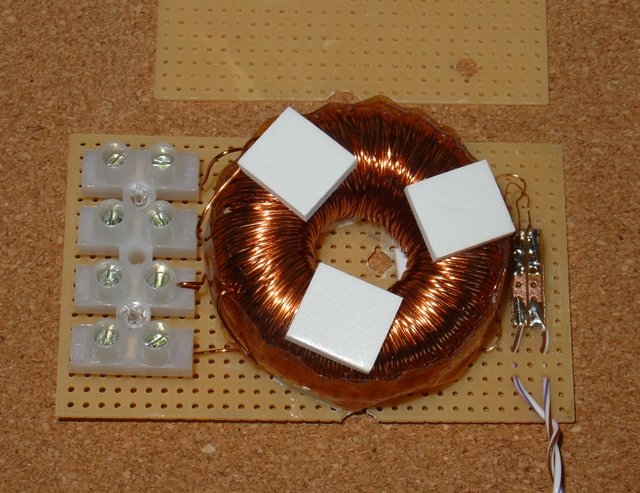

A daughter board was used to mount the full wave rectifier and RL.
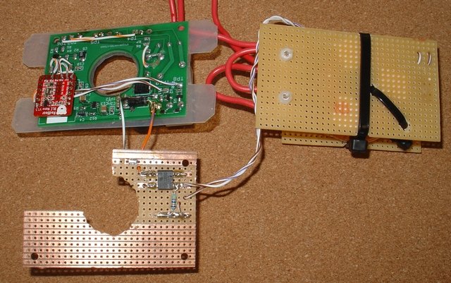
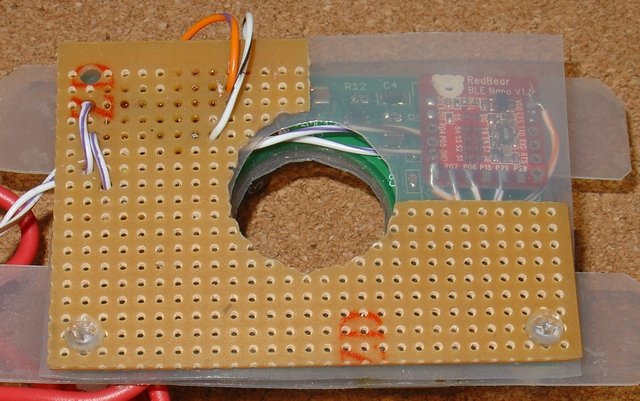

The surge suppressor was a late addition. When I first tested the full circuit with a 0.9A load, I heard a sharp crack when using pfodApp to remotely turn the load on. Closer inspection found a small blue discharge from RL during turn on. When turning on the whole 240V RMS (340V peak) was being applied across the primary of the toroid during the transient. The secondary, with at turns ratio of 2 : 1, was generating up to 680V which was enough to cause a break down between RL and a nearby track. Clearing out the near by tracks and adding a 30.8V AC surge suppressor across the secondary coil solved this problem.
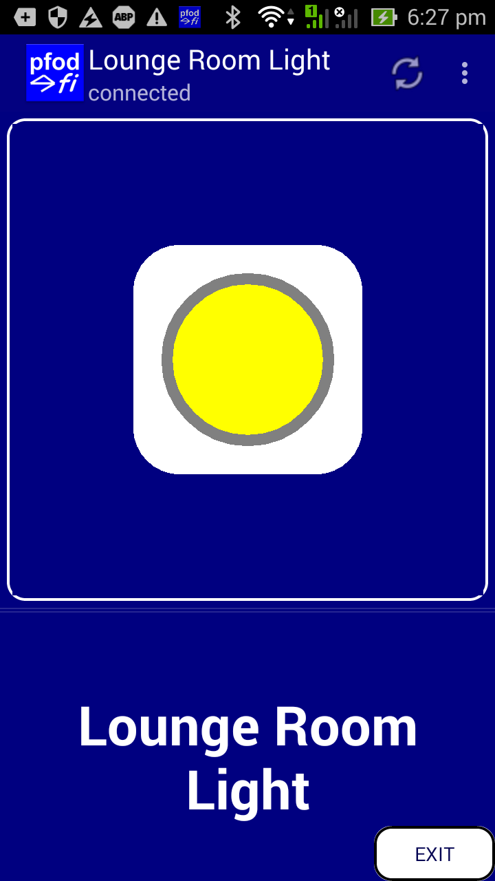
The code in the BLE Nano is the same as that used in Retrofit an Existing Light Switch with Remote Control and that project discusses the code and how to program the Nano. The only change was to the BLE advertising name and the prompt displayed on pfodApp. Connecting via pfodApp from the Android mobile displays this button.

The circuit monitors the voltage applied to the load to correctly display a yellow button when the load is powered up either by the remote switch or by the manual override.
This project extends Retrofit an Existing Light Switch with Remote Control to allow you to remotely control kilowatts of load by just adding this circuit to the existing switch. No extra wiring is required and the original switch continues to operate as a manual override while still allowing you to remotely turn the load ON after you have used the manual override switch to turn it OFF
If the remote control circuit should fail, or you cannot find your mobile, the manual override switch continues to work.
Going forward, retrofitting your house light switches with BLE Nano V2 control modules that supports Bluetooth V5 means in the future you can set up a house wide automation network using a Bluetooth V5 Mesh.
AndroidTM is a trademark of Google Inc. For use of the Arduino name see http://arduino.cc/en/Main/FAQ
The General Purpose Android/Arduino Control App.
pfodDevice™ and pfodApp™ are trade marks of Forward Computing and Control Pty. Ltd.
Contact Forward Computing and Control by
©Copyright 1996-2020 Forward Computing and Control Pty. Ltd.
ACN 003 669 994