
|
Home
| pfodApps/pfodDevices
| WebStringTemplates
| Java/J2EE
| Unix
| Torches
| Superannuation
|
| About
Us
|
|
|
ESP8266 Wifi Add on for Arduino
|
by Matthew Ford 6th June 2015 -
©
Forward Computing and Control Pty. Ltd. NSW Australia
All rights
reserved.
An
Easy to Use ESP8266 WiFi
|
|
These
instructions have been superseded by
An
ESP8266 based WiFi Shield for Arduino and other micros. This page
describes the first iteration of that project.
You should also
check out the simpler project Cheap/Simple
Wifi Shield for Arduino and other micros which uses Adafruit's
HUZZAH ESP8266 module and is the preferred solution.
For another (simpler) method for setting your WiFi network settings see ESP-01 Timer Switch TZ/DST Updatable Without Reprogramming which automatically goes into setup mode if it cannot connect to the network and has a QR code for easy connection to the setup access point.
ESP8266 is a low cost wifi enabled chip. It comes in a variety of module types and can be programmed in a variety of ways.
This web page will cover setting up an ESP8266-01 module as a simple UART-WiFi pass through. Once set up you can simply connect it to your Arduino and send and receive data via a serial port. No AT command required (or allowed). Also with this set up, you never need re-program the module with network parameters, like ssid, password, staticIPs or portNo, as once you have flashed the module, you can configure it via WiFi using pfodWifiConfigV1.
If you are looking for a way to generating code and program (Arduino style) natively ESP8266-06 style modules mounted on PCBs such as OLIMEX ESP8266-EVB and Adafruit Huzzah and SparkFun ESP8266 Thing. Then check out ESP8266 and pfodApp™ Code Generator instead. Note: pfodApp and ESP8266 needs pfodParser library V2.7+
This project has the following features:-
Uses the inexpensive ESP8266-01 module
The ESP8266-01 only needs to be flashed (programmed) once (via Arduino IDE). Thereafter you can change the WiFi config and staticIP/DCHP and portNo via WiFi using pfodWifiConfig
Connects to your Arduino board via the UART at 115200 (using Serial or Serial1) and transparently passes data to and from the WiFi connection. No messy AT commands needed.
This gives you an inexpensive way of adding WiFi to your Arduino project and, using pfodWifiConfig, makes it easy to add to your network and configure its connection (ip/port). This project sets up the ESP8266 as a server listening on a configurable port, but pfodWiFiConfig also supports configuring devices as clients that connect to a host with a logon.
Here are the parts used in this example project.

An the ESP8266-01
3.3 Volt Arduino compatible, Teensy-LC . Using a 3V3 based Arduino simplifies connecting to the ESP8266 which only accepts 3.3 Volt inputs. You can use 5V Arduino boards but you need to add level converters on the TX/RX pins to connect to the ESP8266-01
A 3.3V supply for the ESP8266 that can deliver 250mA. Most Arduino boards (like the Uno and Mega) are not designed to supply this much current via their 3.3V output pin, so you need to add another power source. Here I have used the inexpensive DFROBOT 5V/3V3 supply board.
The free pfodWifiConfigV1 Android App OR a computer and telnet.
Total cost for these components is about US24 (plus shipping and a 5V 1A supply)
In addition to these components, you will need a USB to 3.3V Serial adapter to re-flash the ESP8266-01. I used OLIMEX's USB Serial Cable F, but SparkFun also has similar cable USB to TTL Serial Cable 3.3V (don't use the VCC lead which is 5V), and suitable boards, like FTDI Basic Breakout – 3.3V board.
As delivered, the ESP8266-01 module comes with an AT command interpreter which lets you configure the module and send/receive data using AT commands. This is a very messy process and prone to error. (However if you want to use AT commands check out this project, Code Generator for ESP8266-01 using AT commands)
In this project the ESP8266-01 is programmed, just once, to set it up as a transparent WiFi connection that can be configured via WiFi.
To setup to program the ESP8266-01, follow the steps given on https://github.com/esp8266/arduino under Installing With Boards Manager. When opening the Boards Manager from the Tools → Board menu and select Type Contributed and install the esp8266 platform. This project was compiled using the ESP8266 version 1.6.4-673-g8cd3697. Later versions well be better but may have their own bugs as the platform is evolving rapidly.
That is the software installed. To connect the ESP8266-01 for programming you need to wire up a 3.3V supply and a 3.3V USB to Serial cable and a means to short GPIO0 to GND. The readme on https://github.com/esp8266/arduino has one such configuration.
Here is the circuit I used to program the ESP8266-01.

To re-flash the ESP8266-01 you need to install the pfodWifiConfig supporting libraries. Two supporting Arduino libraries are needed pfodWifiConfig.zip and pfodWifiConfig_ESP8266.zip.
Once these libraries are installed you can select Board-> Generic ESP8266 Module. The load this sketch, pfodWifiConfig_ESP8266_PassThrough.ino This sketch turns the ESP2866 module into a UART-WiFi bridge which can be configured over WiFi by pfodWifiConfig. This sketch is also in the examples directory of the pfodWifiConfig_ESP8266 library.
Start by preparing your own pfodWifiConfigV1 QR code containing your own temporary access point password. The example sketch uses this QR code
 You
should generate your own and update the sketch with your password
You
should generate your own and update the sketch with your password
//
update this define with the password from your QR code
//
http://www.forward.com.au/pfod/pfodWifiConfig/pfodQRpsk.html

#define
pfodWifiConfigPASSWORD "plyWtEDk6uZ0yfmAEM5wMc"

//
the ssid is "pfodWifiConfigV1" and the port is 23 -- set by
pfodQRpsk program
The ssid and password contained in this generated QR code is the one the ESP8266 module will use, in config mode, to connect to the temporary access point in order to be configured.
Once
you have generated your own QR code and updated the
pfodWifiConfigPASSWORD
in the sketch, program the ESP8266 module with
pfodWifiConfig_ESP8266_PassThrough.ino
by connecting the USB-Serial cable to 3 pin header (MA03-1) and then,
with the power off, short out JP1 (i.e. connect GPIO0 to GND) and
then apply power. Once power is applied you can remove short.
Then you can click the download button on the Arduino IDE to compile and download the sketch.
That's it. Finished. You won't need to re-program the module again. Keep a copy of the QR code for configuration, below.
Once the Module has been programmed with the pfodWifiConfig_ESP8266_PassThrough.ino sketch, you can configure its WiFi parameters and DHCP/StaticIP and server portNo via pfodWifiConfigV1.
To do this first install the free Android app pfodWifiConfigV1 from Google Play. If you don't have Google Play on your mobile you can install the app from SlideMe. If you don't have an Andoid mobile you can still do the configuration from a computer using Telnet.
Then start the pfodWifiConfigV1 app.

Then
press the Scan QR Code button and scan the QR code. This code is used
to open an Access Point on your mobile.
NOTE: Some network providers attempt to
prevent you creating an Access Point on your mobile, depending on
your contract. If the pfodWifiConfigV1 app cannot create an Access
Point on your mobile you will have to use the Telnet
option to configure your device.
Now
power up the ESP8266 module and within 20 seconds short GPIO2 to GND
via a 270ohm resistor. The resistor protects against shorting GPIO2
when it is configured as an output. NOTE:
Very important DO NOT connect GPIO2 to GND before power up the module
as this will prevent the module from running the sketch.
When the ESP8266 module connects to your mobile's temporary Access Point, the pfodWifiConfigV1 displays the available configurations as defined in the sketch you loaded into the ESP8266 module. In this case the available configuration is as a server with either DHCP or StaticIP and portNo for the server to listen on.

If
you want to use DHCP, click the STATICIP drop down and change it to
DHCP.
Here is an example filled in with dummy data.
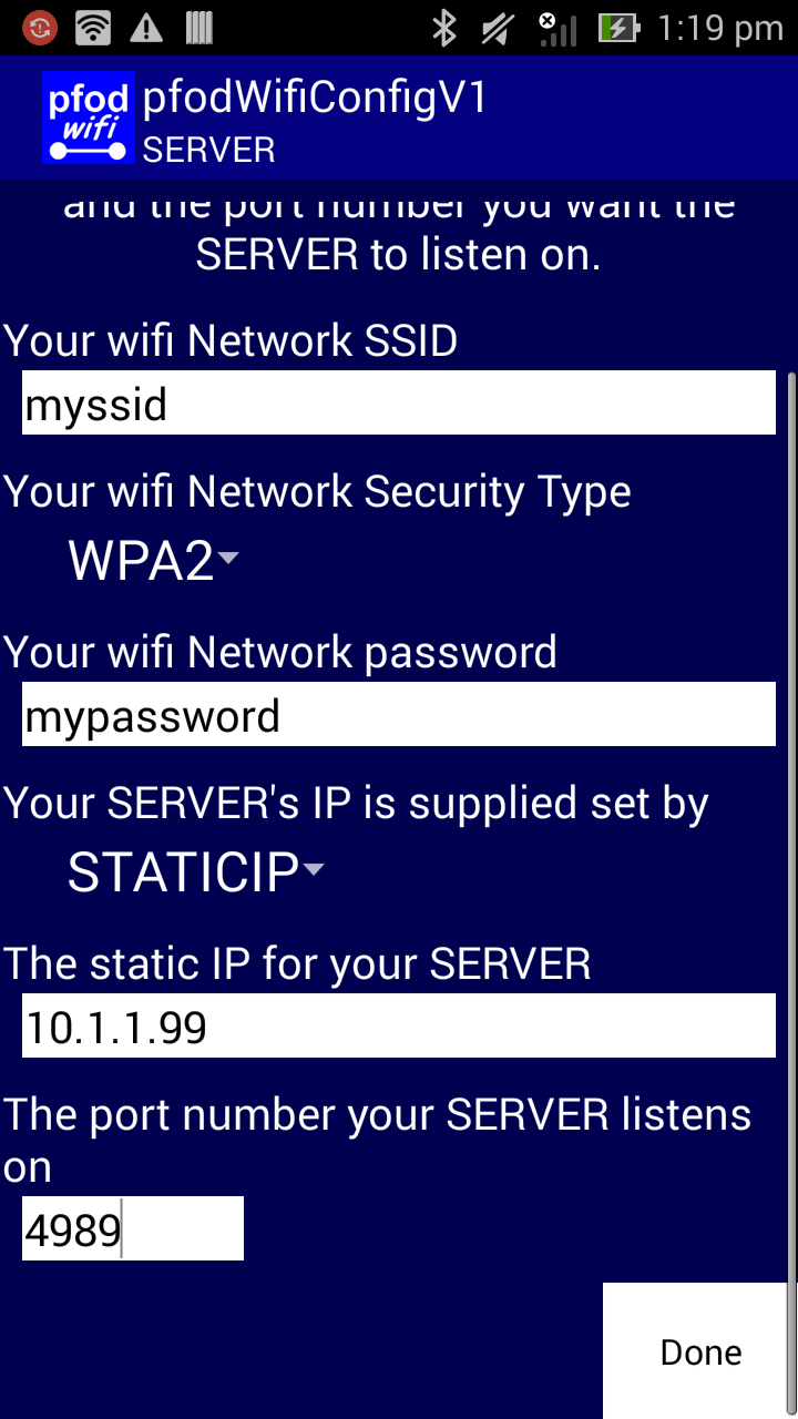
Clicking
“Done” sends the data to the EPS8266 to be saved in
EEPROM, and displays the following screen.

Note
the simple text message sent to the ESP8266
{set
myssid WPA2 mypassword 4989 10.1.1.99 }
If you were using telnet to configure the module, this is the type of message you would send. See the pfodWifiConfigV1 protocol definition for the format of the {set commands.
Now remove the connection from GPIO2 to GND and power cycle the ESP8266 module to connect to your network using a static IP of 10.1.1.99 and with it listening on port 4989 for connections.
Here is an example hardware set up connecting an ESP8266-01 in pass through mode to a Teensy-LC, both powered from a DFROBOT 5V/3V3
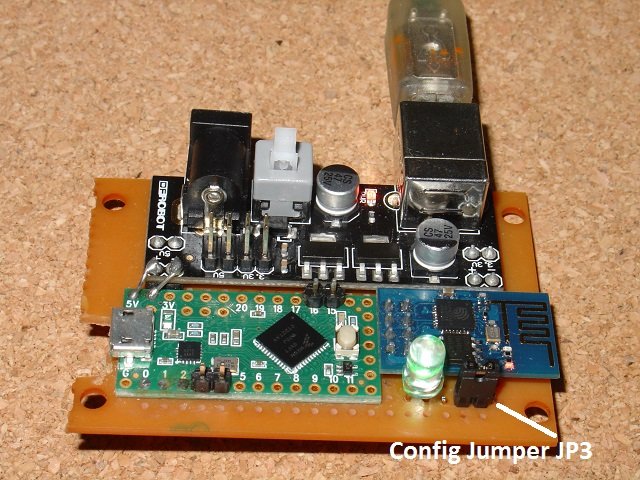
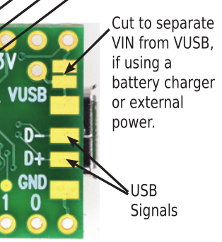
The config jumper, JP3, for grounding GPIO2 (via a 270ohm resistor) is shown bottom right, next to the config Led which is lit when the module is in pfodWifiConfig mode. The Teensy-LC VIN-VUSB track was cut, as shown above because the Teensy-LC is being powered from the DFROBOT power supply.
Here is the full circuit. The resistors and JP1 and MA03-1 headers are all mounted in a rats nest under the vero-board.

Once the ESP8266 has been programmed it acts as a UART-WiFi bridge. To demonstrate that, here is an Arduino sketch (TeensyPassThrough.ino), created with pfodDesigner. When the pfodDesignerV2 generated the code for this sketch the connection was specified as via Serial1 at 115200 baud. This sketch works with pfodApp to let your Android turn the Teensy LED on and off via WiFi. Note when you inspect the sketch, TeensyPassThrough.ino, you will not find any WiFi configuration, just read and write to parser connected to Serial1 which connects to the ESP8266 module at 115200 baud.
To code the Teensy-LC you need to install the Arduino IDE V1.6.3 or V1.6.4. I used V1.6.3. Then download teensydunio.exe and run it to install the Teensy addon and drivers. Then select Teensy-LC from the Tools->Boards. The first time you program the board you may need to press its Reset button. After the first time I usually did not need to do that.
After you load the sketch, install pfodApp on your Android mobile and setup a connection for the IP and port that you configured with pfodWifiConfigV1 on the ESP8266 module (see pfodAppForAndroidGettingStarted.pdf for setting up pfodApp connections). On connecting, the sketch will send back this menu for you to control the led on the Teensy-LC board.

This tutorial has shown how to flash the ESP8266-01 module as a UART-WiFi bridge with support for pfodWifiConfigV1. Using pfodWifiConfigV1, you never need to re-flash the ESP8266-01 module to set or change the WiFi and IP/port settings. You can change those via WiFi using the free pfodWifiConfigV1 app.
An example application using this pass through ESP8266 module, was also shown. That sketch was created using pfodDesigner, which generated the necessary code to switch the Teensy-LC led on and off from pfodApp on an Android mobile.
AndroidTM is a trademark of Google Inc. For use of the Arduino name see http://arduino.cc/en/Main/FAQ
The General Purpose Android/Arduino Control App.
pfodDevice™ and pfodApp™ are trade marks of Forward Computing and Control Pty. Ltd.

Contact Forward Computing and Control by
©Copyright 1996-2020 Forward Computing and Control Pty. Ltd.
ACN 003 669 994