
|
Home
| pfodApps/pfodDevices
| WebStringTemplates
| Java/J2EE
| Unix
| Torches
| Superannuation
|
| About
Us
|
|
|
Retrofit House Lights with WiFi - Keep existing switches
|
by Matthew Ford 8th Nov 2016 (originally
posted 25th Sept 2016)
© Forward Computing and
Control Pty. Ltd. NSW Australia
All rights reserved.


Update 8th Nov 2016 – Updated with changes made to Retrofitted Fan Timers project.
Unlike commercial remote controlled lights, this project retrofits WiFi control (ESP8266-01) in parallel with the existing light switch. That is the existing light switch and the remote control both can turn the light on and off. You can use the existing light switch to turn the light off and then use the WiFi remote to turn it back on again. An example use is for a back porch light that you want to be able to turn on from the shed so you don't have to walk back in the dark, but you also want to just use the normal light switch to turn the light on and off when you are in the house.
Three versions of the project are described. The first version uses exactly the same circuit as the Retrofittred Fan Timers and has the hardware mounted in the same box. The second version re-configures the hardware in a long snake form for easier installation though small holes into tight ceiling spaces. The third version uses a simpler and more robust circuit which allows you to continue to control the light from the wall switch even if the remote control hardware fails. All versions include a web page configuration that makes it simple to connect it to your home WiFi network.
Only a simple modification to the existing light wiring is needed to install the remote control, in most installations, no extra mains wiring is needed for Versions 1 and 2. This project also works with hall lights that have with double switches, one at each end of the hall.
For Versions 1 and 2, the trick to this project is that an opto-isolator is used to detect when the light switch is turned on and off. Each time the light switch is switched (either on or off), the relay controlling the light is toggled. The remote control, via pfodApp, displays the current state of the light on or off and can also be used to toggle the power relay. After this remote control is installed, the existing light switch operates like a hall light switch. Each time you change the switch position the light changes on/off. Using the pfodDesigner you can also easily add timer to the remote software to turn the light off after a fixed time.
For Version 3 the trick is that the Remote Controlled Relay acts like the second switch for a hall light with two wall switches.
This project changes the use of the existing mains wiring in your house. You need to get an electrician to do these changes and you do these changes at your own risk. . The hardware uses mains power and should only be attempted by experienced constructors. The hardware does not use an earth and is protected by double insulation, but it has not been certified by any standards authority and so may void your house insurance if it causes a fire. The hardware has been designed so it can be tested without using mains power. Carefully note the safety points detailed below.
To operate the light from the existing wall switch, just operate the switch like a hall light switch. That is if the light is ON and the switch is UP, switch DOWN to turn the light off. If the switch was DOWN, and the light ON, switch UP to turn the light OFF.
To operate the light remotely (after setting up the
pfodApp connection as described below), start pfodApp, it will
automagically connect to the light if that is the only connection
defined. pfodApp will display this screen with the current state of
the light. You can modify this display's text, colours etc using
pfodDesignerV2.
Click
anywhere in the button to toggle the light On/Off. This will override
the wall switch. You can use the wall switch again to override the
remote control and the pfodApp will update with the new state of the
light On or Off.
Once you have constructed and installed the hardware, for remote control you need to connect it to your WiFi network and then create a connection in pfodApp to control it. The wall switch continues to work even if you are not connected to your WiFi.
To connect to your WiFi network you need to configure the hardware with your network's name and password. To do this :-
Turn the mains power to the light off for 20sec and then turn it back on
On power up, the ESP8266 module will create its own WiFi hotspot for 10mins. You can set the name of this hotspot in the code, here I have called it “Porch Light Setup”. The light will come on. You can also exit the configuration mode by just turning the light off.
Connect to the hotspot with your Android (or IOS mobile). After a few seconds you will be prompted to 'Sign in to WiFi hotspot', which will display the setup page for the Light Remote.
If you are not prompted, then open a web browser and type in http://10.1.1.1. The setup page will have pre-filled in the strongest WiFi signal it can find. You can edit it if you need to. The configuration is save in non-volatile memory so you don't need to re-configure if you have a blackout.
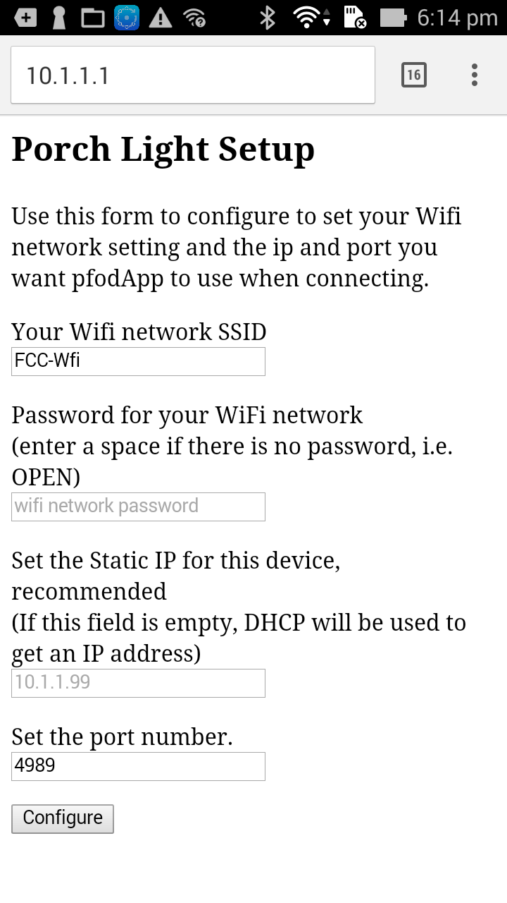
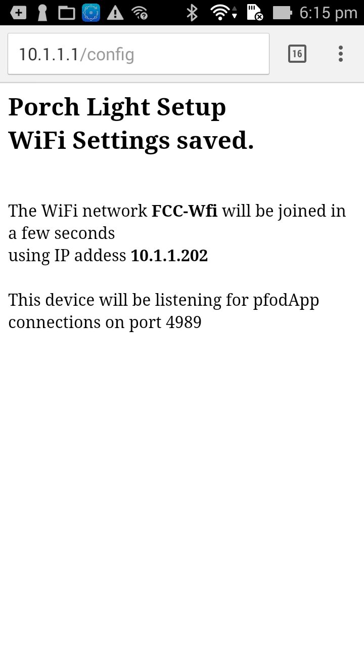
When
you have filled in the password and the ip address you want to use,
click the Configure button which will display the saved settings,
shut down the hotspot and, after a few seconds, turn off the light
and connect to your WiFi network
Follow
pfodAppForAndroidGettingStarted.pdf
to setup a connection for the ip and port you have configures. The
you can connect with pfodApp and control the light remotely.
The code given below has empty passwords for the WiFi
hotspot and the pfodApp connection. You are encouraged to add a WiFi
hotspot password
#define
pfodWifiWebConfigPASSWORD "hotspotPassword"
so
that no one can eavesdrop on the connection when you configure your
WiFi network password.
If you wish you can also password
protection for the pfodApp remote control.
#define
pfodSecurityCode "remotePassword"
pfodApp
uses a simple but effective security
system described here. If you configure your home WiFi router, as
described here, so you can control the light from anywhere in the
world, then you should use a pfodSecurityCode to control access to
the light.
Version 1 of this project uses exactly the same circuit and construction as the Retrofitted Fan Timer project. Refer to that project for the parts list and construction details. The difference here is the software and how the hardware is installed.

The power switch is programmed as a pfodDevice and is controlled by pfodApp on your Android mobile. pfodApp is a general purpose application, the one pfodApp can be used to control all your pfodDevices. No Android programming is required.
The basic mobile interface was created using the free pfodDesigner and programmed using the Arduino IDE with the ESP8266 add on. You can customize your own Android menu using pfodDesigner. See this tutorial on using pfodDesigner to control a digital output. In this project, D3 is the output controlling the relay connected to the light and a menu refresh every 1sec is added to show the current state of the light. Here is the code generated by pfodDesigner. It displays this menu on pfodApp and allows you to turn the relay on and off.
Once
the basic on/off slider button code is generated, it is modified to
add the input from the opto-isolator to toggle the light on/off and
to add the webpage configuration. Here
is the final code for versions 1 and 2.
SAFETY NOTE: DO NOT plug in the power cable. All programming and program testing/debugging can be done without applying mains power.
To compile the ESP8266_LightRemote.ino sketch you will need to install three libraries, pfodParser.zip from the pfod Library page, pfodESP8266BufferedClient library V2.3 and the DebouncedSwitch library V3.0.
Then follow the Software Programmed instructions given in the Retrofit Fan Timer to load the ESP8266 with ESP8266_LightRemote.ino
Once you have completed the software programming and testing using a 5V supply, you can seal up the enclosure and do a final test using AC power before installing the remote in the roof space.
WARNING – Mains Power can Kill You. Do not apply Mains power unless the enclosure is completely sealed and all the plugs and sockets are connected and closed.
To test the light remote, temporarily fit plugs and sockets as shown in the Retrofit Fan Timer project. Then plug it into a double power point, starting with both switches off, and plug a lamp into the controlled plug base (socket) as shown below.

The
single power cable (yellow above) will pickup the power from the
existing wall light switch. With this setup you can do a complete
functional test using the power switch connected to the single
(yellow) cable to simulate the wall light switch.
After final testing, you can remove the plugs and sockets and arrange for an electrician to install the remote in your ceiling or under the eave next to the porch light. Here is a schematic of a typical existing switch light and light (pdf).

Active,
Neutral and Earth wires are often looped from light base to light
base. For each light the Active is looped down to the wall switch and
back to the lamp base to power the light when the light switch is
turned on.
Here is the modified wiring after installing the Light Remote. (pdf) Basically all the connection can be done at the light base without running any new cable. Tap into the Active/Neutral to power the Light Remote and then disconnect the switched Active powering the existing light and loop it into and out of the Remote.

There
are also many other ways to wire up lights but your electrician
should be able sort it out.
This is a prototype of a thin version of the hardware
Instead
of being mounted in a box it is arrange is as a long snake so that
when suitable insulated it can be pushed into the wall/roof cavity
where the light fitting is. The circuit, software, and mains wiring
installation is the same as for Hardware – Version 1.
Version 3 of the Light Remote has a simpler and more robust circuit, but requires a bit more installation and does not display the current state of the light on the mobile remote menu. The advantage of Version 3 is that if the Light Remote hardware fails you can still operate the light from the existing wall switch.
While the Android remote control (pfodApp) no longer displays if the light is on or off. This control is still suitable for common situations where you can visually see if the light is on or not.

Here
is the circuit for Version 3 (pdf)

In
this circuit the relay acts exactly like the second hall switch as if
you were wiring up a hall light with two switches.
You can construct this circuit using either of the Hardware constructions for Version 1 or Version 2 (above)
A lot of the existing code from Versions 1 and 2 is not needed/used for Version 3, but to simplify the changes, I just modified the pfodApp menu to remove the indication of the light state. So program ESP8266_LightRemote_V3.ino sketch to complete the construction.
As for Versions 1 and 2, for the first 10mins after applying mains power the Light Remote will turn the light on and provide a WiFi hotspot for configuring your WiFi network parameters. The hotspot, and the light, will turn off after 10mins or after you have finished the configuration. If you turn the light off with the was switch in the first 10mins after applying power, it will turn on again when the hotspot stops.
Here is the modified mains wiring after installing Version 3 (pdf). Note: You need a 2-way wall switch (most are) and you need to run an extra wire from the wall switch to the Light Remote, for In from Wall Switch (B)

That's
it. If the Light Remote fails or the relay contacts weld closed, you
can still control the light using the existing wall switch.
This project presented three (3) Remote Light Controls that could be retrofitted to existing lights and which retained the operation of the existing wall switch. The third version is particularly robust and allows continued operation of the light via the existing wall switch even if the Light Remote hardware fails.
AndroidTM is a trademark of Google Inc. For use of the Arduino name see http://arduino.cc/en/Main/FAQ
The General Purpose Android/Arduino Control App.
pfodDevice™ and pfodApp™ are trade marks of Forward Computing and Control Pty. Ltd.

Contact Forward Computing and Control by
©Copyright 1996-2020 Forward Computing and Control Pty. Ltd.
ACN 003 669 994