
|
Home
| pfodApps/pfodDevices
| WebStringTemplates
| Java/J2EE
| Unix
| Torches
| Superannuation
| CRPS Treatment
|
| About
Us
|
|
|
EV Charger/V2L Switch with Web Interface
|
by Matthew Ford 29th March 2026 (originally posted 31st January
2026)
© Forward Computing and Control Pty. Ltd. NSW
Australia
All rights reserved.
Switch between recharging your EV or using its battery to power your house
Manual control or remote control via web page
Add timers to auto switch on charging or powering the house
No reprogramming required to connect to your WiFi network or to set your timezone (including daylight saving)
Syncs to internet time or run completely off line with RTC_NTP_replacement
Update: 29th March 2026 – Added turning Charger on to the
sequence for turning on V2L as Inster sometimes did not otherwise
enable V2L
Update: 2nd March 2026 – Add RC
suppression to 240V relay
Update: 12th February 2026 –
increased time delays between switches. Greyed out web page
background when changes blocked due to time delays.
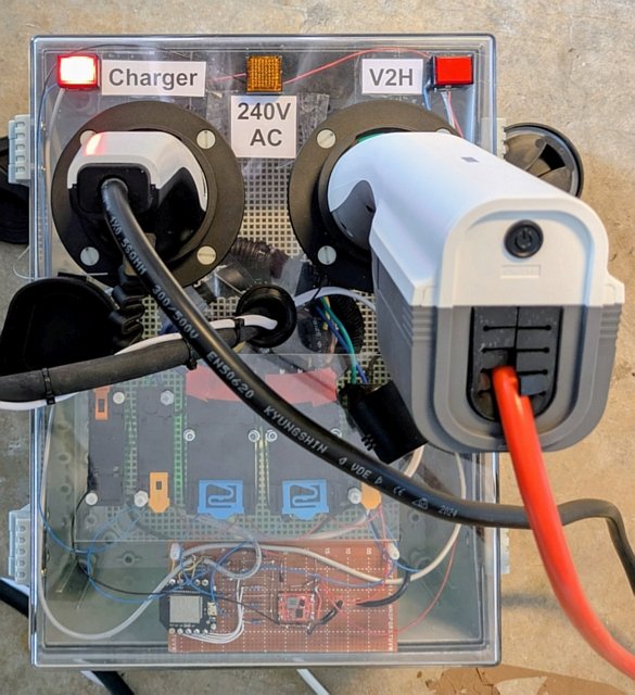
This EV Charger / V2H Switch is a box that you plug your Type 2 Charger and Type 2 V2L (Vehicle to Load) connector in to and the plug its cable into your EV so you can remotely switch between charging your EV or using your EV's battery to power the house. The switch box lets you activate either plug manually (at the switch box) or via a web page or at specified times. The Auto timer control for each plug allows you to set a time during the day that you charge the Electric Vehicle (EV) or turn on the V2L supply. This switch requires that your EV can supply V2L power via the external Type 2 charging socket. In this project the EV used is an Hyundai Inster which can supply up to 3.6kW of V2L power.
Combine this EV Charger / V2H Switch with the Vehicle to House project to use your EV to power your house at the times of day you specify. Here V2L and V2H are used interchangeably since the V2L output from the EV is being used to power the house.
The EV Charger / V2H Switch can accommodate single phase Type 2 chargers up to 7.5kW / 240VAC. The V2L is single phase and can be up to 7.5kW / 240AC, but for the Hyundia Inster the V2L output is limited to 3.6kW. Other Evs may bave lower V2L limits.
Adding an additional 30A relay and changing the switch box sockets and output cable to 3 phase would allow for 3 phase charging up to 22kW. The V2L connection is only single phase.
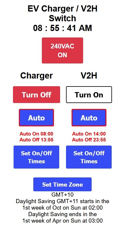
The web page interface allows you select between Charger or V2L plugs or turn them On/OFF. The AUTO mode allows you to choose the times of the day the each plug is selected and turned On or Off.
Setting up your time zone and connecting the EV Charger / V2L Switch to your local network are all done via web pages, without re-programming. The web pages are laid out for mobile phone use. If you provide access through your router, you can control the EV Charger / V2L Switch over the internet. The time zone setup includes automatic daylight saving adjustments and the time is set from the internet (SNPT server) so the on/off times remain accurate through summer and winter. However you can also, optionally, use the RTC_NTP_replacement project to run completely off-line, without any internet connection.
For a simpler project to charge your EV as specified times of the day see, EV Charger Timer
This project involves mains power wiring and high currents, it should only be undertaken by experienced constructors.
Hardware
1
x IP66 Electrical Plastic Enclosure ABS Power Junction Box 400mm
x300mm x 200mm with transparent cover from Aliexpress ~US$41.60
2
x EVSE IEC 62196-2 Type 2 Male Socket 1 Phase, 32A from Aliexpress
~US$26.00 each
1 x Khons EV Charger Type2 Female Car Side 5m Cable
32A 1 Phase 7kW from Aliexpress ~US$50.00 (cut off the cable to use
between switch and EV)
1 x FITMPH Type 2 EV Female Charger
Connector from Aliexpress ~US$20.00 (incl shipping) (wire the cable
from khons into this connector)
2 x G30F-3ZLD-A 12V 3 pole
changeover relay 12V coil ENMG Compact High Power Relay Flange
Mounting G30F High Current 30A from Aliexpress ~US7.50 each
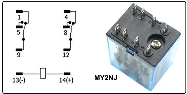
2 x
DC12V MY2NJ 2 pole changeover relay 12V coil 5A contacts from
Aliexpress ~US$2.50 each
1 x 220VAC MY2NJ 2 pole changeover relay
220V coil 5A contacts from Aliexpress ~US$2.50 each
1 x 12V 2A
mains power supply from Aliexpress ~US$4.50
2 x Momentary push
button Red with 12V indicator (all plastic) – e.g. Jaycar
SP0741 ~US$12 each
1 x Orange 12V indicator (all plastic) –
e.g. Jaycar SL2694 ~US$2.00
4 x 1N5819 40V 1A Schottky Diode or
similar (could also use 1N4001), e.g. Jaycar
ZR1020 ~US$0.55 each
4 x 3k3 1/8W resistors e.g. Jaycar
RR0584 (pack 8) ~US$0.55
1 x 1R0 1/4W resistor – e.g.
Jaycar
RR1502 pack of 8 ~US$0.40
1 x 0.22uF (220nF) 250VAC Metallised
Polypropylene X5 Capacitor – e.g. Jaycar
RG5238 ~US$0.90
1 x DM02_28050016DS EBYTE 7.5V to 28V in / 5V
out 1.6A Amazon ~US$2.80
4 x IRF7805ZP N-Fet (discontinued use
IRLML6346TRPbF Digikey IRLML6346TRPBFCT-ND or similar ~US$0.45)
4
x 1000uF 25V e.g. Digikey 1189-1583-1-ND or similar ~US$0.66 or
Jaycar
RE6328 ~US$1.00
1 x DFRobot Beetle ESP32 SKU:DFR0575
~US$9.90
1 x vero board pre-punched e.g Jaycar
HP9554 ~US$7.40
1 x Unclad Punched Laminate - 150 x 70mm (to
mount 30A relay) e.g. Jaycar
HP9562 ~US$4.70
8 x M4 x 16mm nylon screws e.g. Jaycar
HP0162 (pack of 25) ~US$6.40
8 x M4 nylon nuts e.g. Jaycar
HP0168 (pack of 25) ~US$4.50
8 x M6 x 25mm nylon Screws
Counter Sunk – e.g Bolt
& Nut Australia ~US$13.00
8 x M6 nylon nuts – e.g
Bolt
& Nut Australia ~US$9.30
1 pack 100mm x 2.5mm cable ties
e.g. Bunnings
I/N: 4431104 ~US$1.00
1 x 240V power plug base e.g. Bunning
I/N: 4430736 ~US$2.40 (for 12V supply)
2m White Extension cord
e.g. Bunnings
I/N: 0189129 ~US$2.00 (for 12V supply cut off socket end and wire
to power plug base)
1 x power plug e.g. Bunnings
I/N: 4330079 ~US$3.15
5m twin 7.5A power cable – e.g.
Bunnings
I/N: 0760699 ~US$4.80 (for PP and CP
leads from Switch to EV)
Software
Arduino
IDE V2 (V2.3.6)
data upload add-on arduino-littlefs-upload
ESP32
board support V3.3.3
EV_Charger_V2H_switch.zip
and libraries.zip -- The
source code also needs the following
libraries to be installed via the Arduino IDE Library Manager:-
SafeString V4.1.14+, ESPAutoWiFiConfig V2.2.1, ESP Async WebServer
V3.9.4 and AsyncTCP V3.4.10 and DebouncedSwitch
from its zip file. --- The libraries.zip
contains those files. Unzip to your Sketch directory.
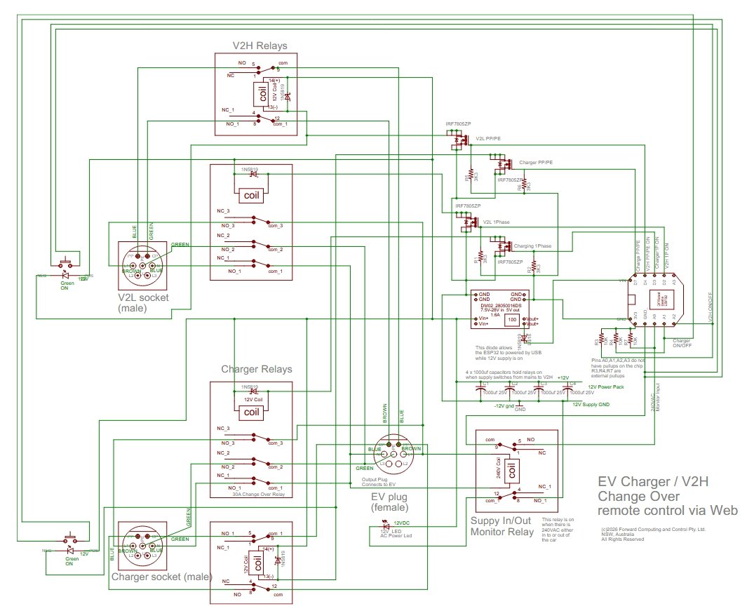
The circuit has a pair of 12V relays for each input (Charger and V2H). The heavy duty 30A relay handles the Active Neutral Earth connections. The other relay handles the PP and CP connections. Another 240V relay monitors the power to and from the EV. The DFRobot Beetle ESP32 board serves the webpages, reads the push button inputs and sequences the relays. If you look carefully at the charging socket on the EV you will see that CP connection is recessed so that it connects last when plugging in and disconnects first when taking the plug out. On turning on an input, the ESP32 first closes the Active Neutral Earth relay and then 2.5sec later closes the PP CP relay. On turning off, the PP CP relay is opened first and then 2.5sec later the Active Neutral Earth relay opens.
There is also a 8sec delay when changing between Charging / V2H or
between turning On, turning Off Charging or V2H
During these time
delays other push button and web page selections are disabled. The
background of the web page is grey when selections are disabled.
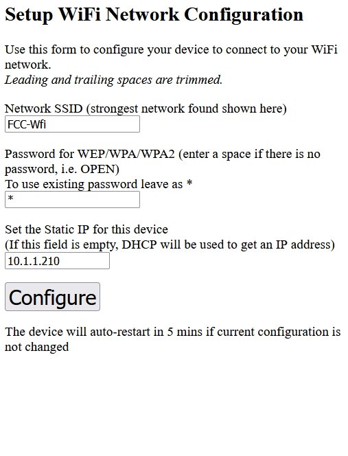
Power up the Switch Box's AC power. The ESP32's green led will flash rapidly indicating there is no connection to your network and that the ESP32 has setup an Access Point, WiFiConfig, for you to connect to configure your network settings. See the ESP-01 Timer Switch project for how to connect to the network using the WiFiConfig webpage.
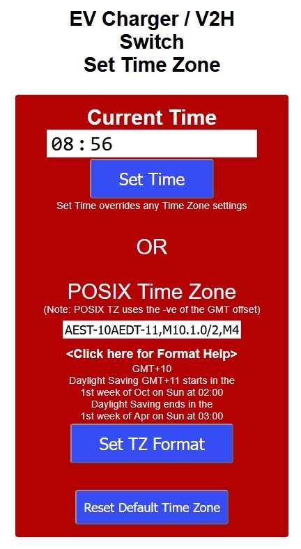
Once you have connected to your network, open the IP address you set for your EV Switch, e.g. http://10.1.1.210, and click the Set Time button and check your correct time zone is set. Also see the ESP-01 Timer Switch project for how to set the time zone.
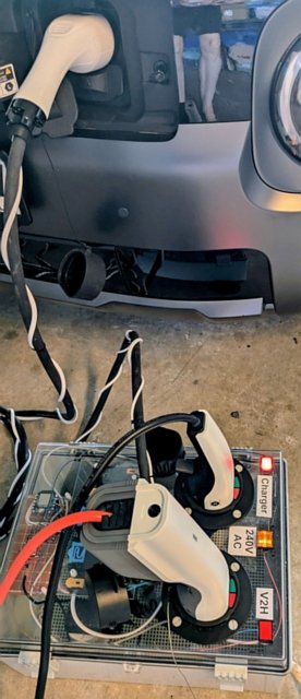
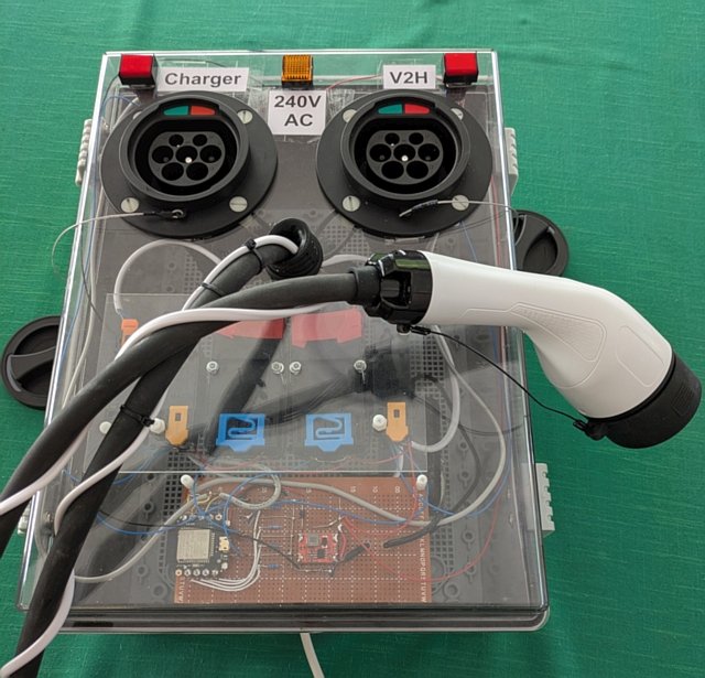
Plug in the Charger and V2L connectors into the switch box and plug the switch box's cable into the EV's charging socket. The V2L connector for the Hyundia has a push button at the back. Make sure it is pressed in the enable the V2L output via this connector.
Press the red push button for the input you want to connect. After
a few seconds both relays will be closed and the button will light
up. If power is flowing in the connection, the Orange 240V AC
indicator will also light up.
To turn the input off, just press
the red push button again.
To change over connections, press the
other connection's red push button. That will disconnect the current
connection and after a few (8sec) seconds later connect the
connection you selected.
When an input is being turned on/off, other button presses and webpage selections are ignored. There is also a 8sec dead time after an input turns on/off where button presses and web page selections are ignored. This gives the EV time to recognize the change states. The background of the web page is grey when selections are disabled.
Click the Turn On button to connect that input. This turns
off the other input first, if is was on. Click the button again, now
labelled Turn Off, to turn that input off.
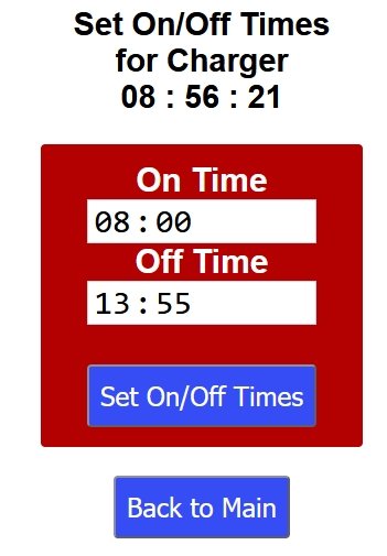
Use the Set
On/Off times buttons to open the web page to set that inputs on/off
times. Click the Auto button to enable the on/off time.
Note: In
Auto, the inputs only turn on/off at the times specified. You can
turn an input off during its On interval and it will stay off until
the next On time.
The 240V AC ON indicator will be red if there is power flowing into or out of the EV.
If the house load exceeds the Inster's V2L capabilities, the EV will shut down the V2L output. For the Hyundia Inster, you can reset this overloadby switching to Charging and then switching back to V2H. Other EV's may operate differently.
The Hyundia Inster locks the switch cable in the EV charging socket once any input is turned on. To unlock it, turn off both inputs and then lock and unlock the EV and open the door. This process works on the Inster. Other EV's may operate differently.
The ESP32 restarts once a day, to clean up any memory leaks. This restart only happens when both inputs are turned off.
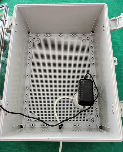
This construction takes care to not
have any metal contact between the outside and inside of the switch
box. All switches, indicators, EV sockets and bolts are insulating
plastic.
Cable ties provide strain relief for the power cables
entering the case.
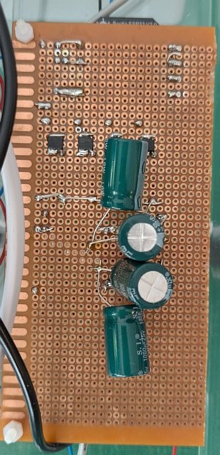
The small smd FETs are mounted on the back of the vero board. The four large (1000uF) capacitors keep the relays operated during the power transients that occur when switching to V2H to power the house.
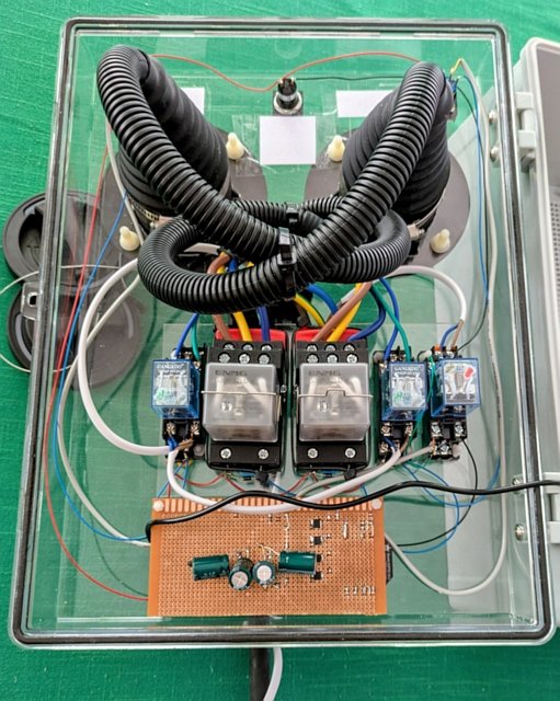
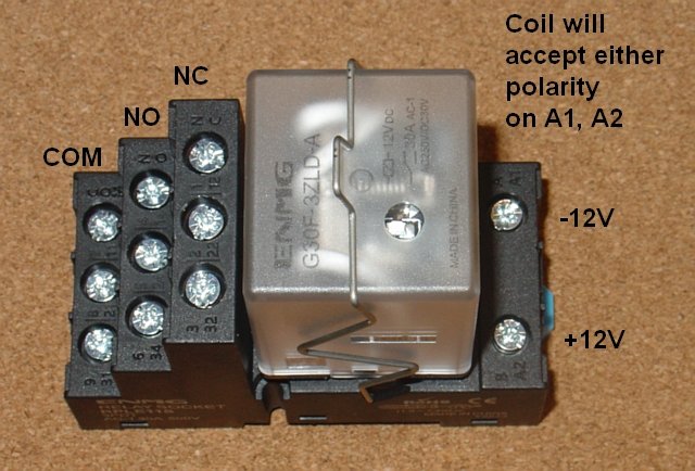
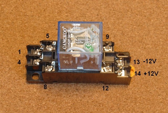
The relay connections are shown below.
Each 12V relay has a flywheel diode connected across the coil to
suppress the turn off voltage spike. The 240VAC relay has a 1R0 +
0.22uF damping circuit connected across its coil.
The relays are
mounted on a daughter perspex panel that is then attached to the
front panel
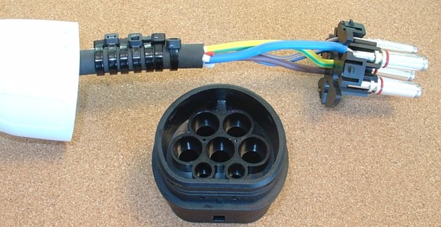
The Khons cable could not be used
directly since is does not provide access to the PP connection. So
the heavy duty cable was harvested from a Khons plug/cable and wired
in to the FITMPH Type 2 EV Female Charger
Connector shell.
The Khons cable is single phase and so
only has 3 heavy duty wires (Active L1, Neutral N and Earth PE). The
L2, L3 unused pins in the FITMPH connector were included in the plug
but left un-connected.
The PP and CP leads to the FITMPH connector
were provided by an additional 0,75mm^2 twin (white) power cable. The
Khons cable only includes a single lead, the CP lead. which was
isolated with heat shrink and left unused.
This twin power cable
was wrapped around the main cable and secured with cable ties. The PP
and CP leads only carry low voltage (+/-12V)
In the Arduino IDE, install the ESP32 board support V3.3.3 board support. Also install the arduino-littlefs-upload Arduino IDE addon.
Unzip the EV_Charger_V2H_switch.zip and libraries.zip to your sketch directory and open the EV_Charger_V2H_switch.ino in the Arduino IDE
Select board DFRobot Beetle ESP32
In Arduino File → Preferences select Show verbose output during upload
To upload the web pages, make sure the Arduino Serial Monitor is closed and press Ctrl+Shift+P to open the tools menu and in the search bar type Upload LittleFS to find the upload tool. Select it to load the data files.
The loop() handles checking switch inputs and sequencing the relays. The web pages are handled by webpages.cpp using the Async WebServer. Since the web page code runs on a different thread, a set of volatile variables guarded, by a lock, are used to transfer the web page Turn On / Off selections to the loop() thread for controlling the relays.
The clock is synchronised via an SNTP server. This requires an internet connection. You can replace the SNTP client with this RTC_NTP_replacement project to run completely off-line.
This project showed how build an EV Charger / V2H switch that can be controlled via a web page. Times can be specified when the Charger or V2H should be connected to the EV. No re-programming is required to connect the switch to your network or to set your Time Zone (including daylight saving times). Both of these are setup via web pages served by the ESP32.
AndroidTM is a trademark of Google Inc. For use of the Arduino name see http://arduino.cc/en/Main/FAQ
The General Purpose Android/Arduino Control App.
pfodDevice™ and pfodApp™ are trade marks of Forward Computing and Control Pty. Ltd.

Contact Forward Computing and Control by
©Copyright 1996-2024 Forward Computing and Control Pty. Ltd.
ACN 003 669 994
 (
(