
|
Home
| pfodApps/pfodDevices
| WebStringTemplates
| Java/J2EE
| Unix
| Torches
| Superannuation
| CRPS Treatment
|
| About
Us
|
|
|
Long Range Radio/LoRa Garage Door Remote |
by Matthew Ford 20th October 2018
©
Forward Computing and Control Pty. Ltd. NSW Australia
All rights
reserved.
This long range in-car remote control is a companion project to Radio/LoRa controlled Garage Door via Android/pfodApp. It allows you open or close your garage door from hundreds of meters away. This remote is sized to slide into the “loose change” tray in our car. The spacers at the back both protect the wire antenna and position the buttons at the from of the tray.
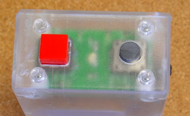
There are only two push buttons, one for Open (the black recessed one) and on for Close (the Red raised one). Unlike other garage door remotes, pressing either button more than once does not stop or reverse the door's motion.
As well as the tactile differences between the buttons, the remote has an audible confirm of which button you have pressed and will alert you if the requested command fails, if out of range for example. A led also provide a visual indication of the state of the control and to indicate when the battery needs re-charging via the USB connector.
Finally a 'zero-off' current circuit uses a FET to completely isolate the battery from the microprocessor/radio when not in use.
Both the Garage Door controller and the in-car remote control use a wire for the antenna. The Garage Door controller's antenna is vertical behind a metal garage door and the in-car remote's antenna is horizontal in the dash board. This is the worst arrangement for sending and receiving radio signals, however even so the in-car controller works some 200m down the road which more then enough for my purposes as it allows me to open the garage door situated at the top of a long steep drive before starting up the drive.
This remote use pfod messages, with 128bit security, to control the garage door. The pfod specification demands that every command from the controller be responded to by the controller, so in-car controller can positively determine if the garage door controller received the command. If the in-car remote is out-of-range, the lack of a response will raise an audible and visual alert in the car.
The first attempt at Radio/LoRa controlled Garage Door via Android/pfodApp used an Adafruit Feather M0 LoRa board. However that board was prone to lock up when mains powered and was replaced with a Teensy/LoRa stack. This in-car remote uses a battery powered Adafruit Feather M0 LoRa board and appears to work reliably. However even it is still not ideal as the Adafruit Feather M0 LoRa board take 2secs to startup after power is applied. This means there is a 2sec delay between pressing either push button and having that command recognized.
This delay was partly overcome by have a 1sec latch in the 'zero-off' current circuit so that you only had to hold the pushbutton down for 1sec instead of 2sec. This was then made a 'feature' of the in-car remote in that it would not respond if the buttons where accidentally bumped.
All in all the Adafruit Feather M0 LoRa board is not recommend. Rather you should use a Teensy 3.2 + Adafruit Teensy Adaptor + Adafruit Radio Feather Wing combination as was done in Radio/LoRa controlled Garage Door via Android/pfodApp This in-car remote only uses an Adafruit Feather M0 LoRa board because I had already purchased three of them.
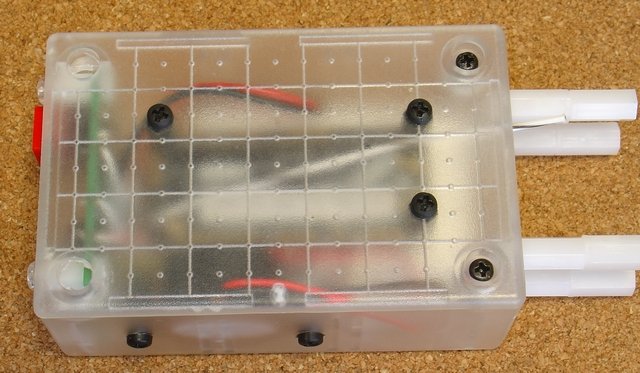
Below you can see the 'zero-off' current circuit board at the bottom with the Close and Open pushbuttons and the indicator led. The black buzzer is driven by the Adafruit's A5 pin used as a digital output.

Here is the 'zero-off' current board, connected to the Adafruit Feather M0 LoRa board and buzzer (a pdf version is here)
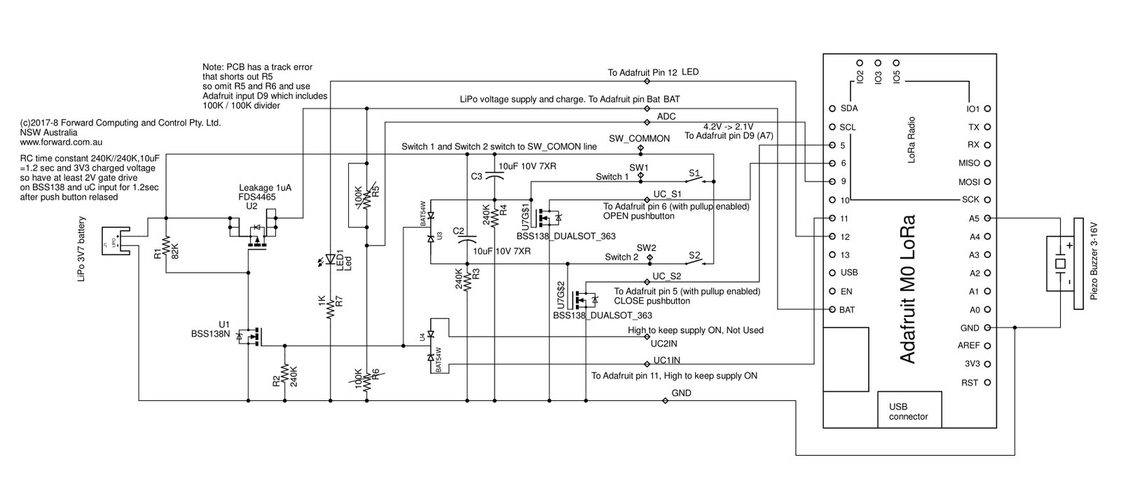
The Gerber files for the small green PCB are available. If you want them contact pfod.com.au via support. However there is a small track error on this version of the board.
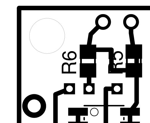 The resistor R5 is shorted out by a track. (See
the short shown in the circuit above) This means the R5/R6 battery
monitor divider is not operational. However Adafruit has a similar
divider attached to D9 to measure battery volts, so by omitting R5
and R6 and connecting the ADC output to Adafruit's D9 the same effect
can be achieved.
The resistor R5 is shorted out by a track. (See
the short shown in the circuit above) This means the R5/R6 battery
monitor divider is not operational. However Adafruit has a similar
divider attached to D9 to measure battery volts, so by omitting R5
and R6 and connecting the ADC output to Adafruit's D9 the same effect
can be achieved.
Alternatively you can construct the 'zero-off' current circuit on veroboard. See Long Life On/Off Remote for the details
The Arduino code for the remote control is in GarageDoor_RemoteControl_b6.zip. Unzip this folder to your Arduino sketch directory. There are a number of files in the GarageDoor_RemoteControl_b6 directory.
The GarageDoor_RemoteControl_b6.ino is the main file. After setting up the various software/hardware components, the loop() method just call check... on each component to let it do its work.
The radio.ino file does most of the work. It initializes the radio, sends the commands, parses the responses and handles connection errors and timeouts. The checkRadio() method does the work.
The debounceSwitch.cpp / .h files handle debouncing of the pushbuttons.
The Flasher.cpp / .h and Buzzer.cpp / .h files handle the various led flashing sequences and buzzer tunes. The Flasher.cpp expects another file to implement the three methods initLed(), led_On() and led_Off() while the Buzzer.cpp expects another file to implement initBuzzer(), buzzer_On(), buzzer_Off()
These extern methods are implemented in the main file GarageDoor_RemoteControl_b6.ino This approach mean the Flasher and Buzzer files need not know anything about the pins used to control the leds and buzzer. In fact initLed(), led_On() and led_Off() control not one but two leds.
There are a lot of timers used in these files. These sketches the new millisDelay to simplify the timer code (actually the duplicate pfodDelay class from the pfodParser library is used). Using the restartChargingTimer as an example, timers in this code typically have three unsigned longs
pfodDelay restartChargingTimer;
const unsigned long RESTART_CHARGING_INTERVAL = 20000; // this is the length of the timer usually a constant
Setting the RESTART_CHARGING_INTERVAL at the top of the code
makes it easier to find and modify the delay if needed.
The
following code starts a timer
restartChargingTimer.start(RESTART_CHARGING_INTERVAL);
The following code checks if the timer has
timed out
  if (restartChargingTimer.justFinished()) {
    // do other stuff here when the delay times out
}Since anyone can listen in to your radio transmissions and record and replay them, when the door control sketch is finally installed, you should set a security password to prevent unauthorized control of your garage door.
To generate a random password and the associated QR code, a SecretKeyGenerator java program is available here which generates random 128bit keys and writes out QR.png files. Another alternative is to use QR Droid Private (from Google Play) to create a QR Code for your own chosen password.
You need to set the same password in both the remote control and the garage door controller. Update the #define near the top of the sketches with your own password.
// add your pfod Password here for 128bit security
// eg "b0Ux9akSiwKkwCtcnjTnpWp" but generate your own key, "" means no pfod password
#define pfodSecurityCode ""
// see http://www.forward.com.au/pfod/ArduinoWiFi_simple_pfodDevice/index.html for more information and an example
// and QR image key generator.
You can then attach the QR code, containing this password, to your door controller module or in some other suitable place.
The remote control does not have a display to tell you what is happening. Instead it uses a led and buzzer to indicated its state.
When you press the Close button the led will light and the buzzer will sound 3 short buzzers to indicated the Close command has been sent. If the Open button is pressed the led will light and there will be 2 long buzzers. In either case if all is well there will be no more sounds and the led will extinguish shortly after the door has reaches the requested position.
After sending the command the remote control continually polls the garage door controller for the door position. Each message the remote controller sends expects a response from the door controller. If the response does not arrive with 4sec, the remote controller sounds one short buzz and resends the message (with the same msg sequence number). After 5 attempts, the remote controller will buzz repeatedly and the led will flash quickly to indicate an error has occurred. If the remote controller succeeds in getting a response within the 5 attempts is resets the count and continues to poll the garage door controller.
The remote controller also checks the time taken for the door to open or close, if the it takes too long after the command has been sent, again the buzzer will buz repeatedly and led flash quickly.
The remote controller is powered by a rechargeable LiPo battery. The Adafruit LoRa board monitors the battery voltage and when the battery volts fall below 3.65V, the remote control will flash and buz erratically after it has finished controlling the door. To recharge the battery just plug in the USB cable throught the hold in the back of the remote control. The led will start to flash erratically to indicate the unit is charging. Once the you have finished charging the unit, after about 8hrs, remove the USB cable, the unit is now still running on the internal battery and still flashing erratically. Press any button once to exit the charging state and shut down the unit.
The garage door controller maintains its own door state, see the Radio/LoRa controlled Garage Door project for the details. When anyone uses the manual door pushbutton to operate the door, the garage door controller's internal state gets out of sync with the real state of door. Usually the garage door controller automatically resyncs itself the next time it is sent a command, but sometimes you need to press the Open pushbutton and then when that has finished press the Close pushbutton (or vise versa) to force the resync.
AndroidTM is a trademark of Google Inc. For use of the Arduino name see http://arduino.cc/en/Main/FAQ
The General Purpose Android/Arduino Control App.
pfodDevice™ and pfodApp™ are trade marks of Forward Computing and Control Pty. Ltd.

Contact Forward Computing and Control by
©Copyright 1996-2024 Forward Computing and Control Pty. Ltd.
ACN 003 669 994