
|
Home
| pfodApps/pfodDevices
| WebStringTemplates
| Java/J2EE
| Unix
| Torches
| Superannuation
|
| About
Us
|
|
|
Arduino for Beginners, controlled by Android
|
by Matthew Ford 16th June 2017 (original
1st September 2013)
© Forward Computing and Control Pty. Ltd.
NSW Australia
All rights reserved.


Note: This page has been
revised to describe the plotting of the Arduino I/Os on your Android
mobile.
If you are updating from the previous version, update your
pfodApp
to V2.1.16 and update your Arduino Uno with this sketch
UnoStarterPlotting.ino.
Copy and past the sketch into your Arduino IDE and upload to Uno
(remove bluetooth shield while uploading)
If this is your first time using UnoStarter, just follow the instructions below. pfodParser library contains the latest version of the UnoStarter.ino as example file under pfodParser.
This page shows you how you can read and write and plot the digital pins on your Arduino Uno and read values and plot from the analog pins all controlled from your Android mobile without doing any coding. This entire project is plug and play. No soldering is required so it is suitable for complete beginners and young pre-teens.
Once you have experimented with turning outputs on and off from your mobile and reading voltages, later projects go on to guide you through some simple code examples you can use to build your own projects controlled from your Android mobile. None of these projects require any Andriod programming. The same pfodApp is used for all the examples. The menus on your mobile are completely controlled by simple strings in your Arduino code.
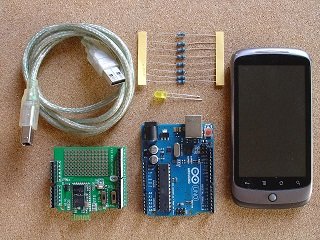
Here is photo of the components you need, in addition to a computer with a USB port. This is the Uno Starter parts list. The cost of parts (excluding the mobile and computer) is approximately US50.00 + shipping.
Here are some screen shots of the mobile's control screens. These screens are completely controlled by the code in the Arduino Uno.

a) Download and install Arduino IDE V1.0.5 from http://arduino.cc/en/Main/Software. That web page has links for various operating systems and a link to GettingStarted (http://arduino.cc/en/Guide/HomePage). Go through the GettingStarted steps for your operating system at the end of which you will have uploaded the BLINK program to your Uno board.
b) Download the pfodParser library. The zip includes the (updated) UnoStarter sketch. Download the pfodParser library zip file and follow the instructions on that page for installing it.
c) Stop and restart the arduino IDE, then under
File->Examples you should now see pfodParser.
Open the
UnoStarter sketch from File->Examples->pfodParser->UnoStarter
and load it into your Uno board. That's it programming
finished.
Hint: When programming the Uno board do NOT have the
Bluetooth Shield plugged in. It uses the same pins as the USB and the
programming gets confused.
d) Download the UnoStarterLabels.pdf and print it out. Stick thin double sided tape to the back of the paper over the labels, then cut the labels out and peel off the tape's backing and stick them on the Bluetooth Shield headers so that the names line up with the markings on the Uno board.


e)
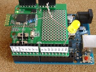
Set the switches on the Bluetooth Shield. Set the 3.3V/5V switch to
5V and set
the To FT232/To Board switch to To
Board. Then plug the shield into the
Uno board (as shown at the top of this page) and plug the USB cable
into the Uno board to power it up.
f) Download and install pfodApp
on your Android mobile (Android V2.1 and above). Follow the
pfodAppForAndroidGettingStarted.pdf
to pair your mobile with the Bluetooth Shield and setup a new pfodApp
connection, I called mine “Uno”.
Finally click on
your Uno connection to connect to your Uno board via bluetooth. The
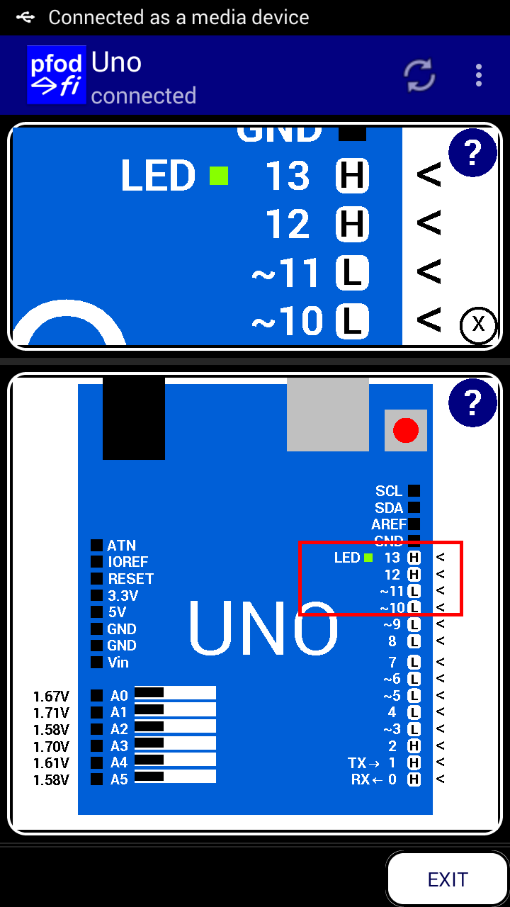
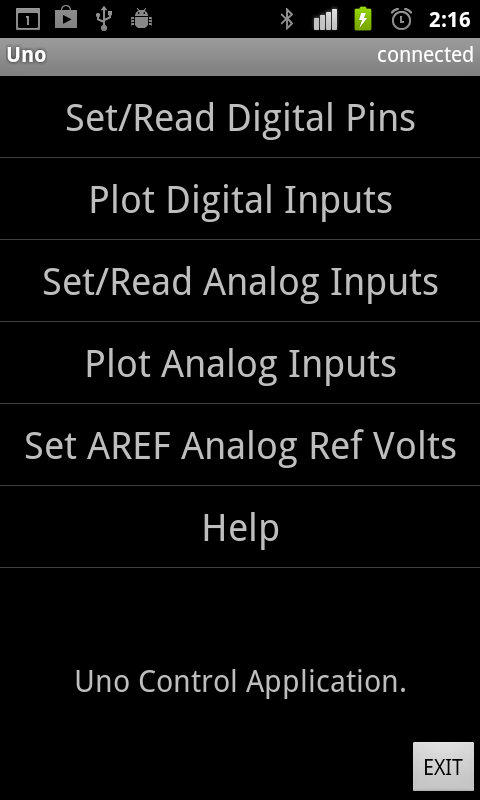
UnoStarter sketch will return this main menu.
Click Digital Pins to read and configure the digital
pins.
Click Analog Pins to configure and read the AtoD inputs.
Click on Plot Digital Inputs or Plot Analog Inputs to see a plot of those inputs. You need to enable at least one of the analog inputs and apply a voltage (<5V) to see an analog plot.
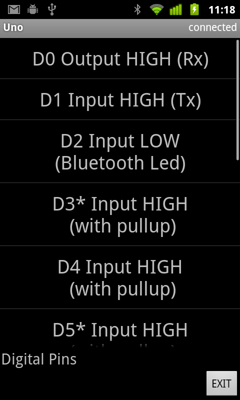
When you click on a Digital or Analog pin menu item, the configuration screen for that pin is returned from your Uno. (See screen shots at the top of this page)
Now that you have constructed your Android Controlled Uno you can try setting pins as inputs and outputs. By default the UnoStarter sketch sets all digital pins as inputs with pullups, except D0, D1 and D2 which are used by the Bluetooth Sheild and cannot be modified.
This project uses 330ohm resistors as connecting wires. Using 330ohm resistors as connection wires protects against shorting out any of the pins. However the wire on these resistors is very thin and you may need to push them to make contact in the header sockets.
Using one of the 330ohm resistors connect D3 to Gnd. The display of the D3 on you mobile will change from HIGH to LOW. The pfodApp on your mobile re-request this screen about once a second.
Move the resistor connection so that D3 is connected to D7. Then click on D7 on you mobile and configure that pin to be OUTPUT LOW. D3 will update to show INPUT LOW.
You need to connect a resistor to the Led to limit the current. Take the longest leg of the Led and bend it up and twist one end of a 330ohm resistor around it. Then plug the remaining leg of the Led into one of the Gnd pins and plug the other end of the resistor into D3.
Now when you configure D3 as OUTPUT HIGH the Led lights. Configuring OUTPUT LOW turns it off. Configuring INPUT with Pullup will turn the Led on weakly because the 20K pullup resistor connects 5V to the D3 input and so supplies some current to the Led.
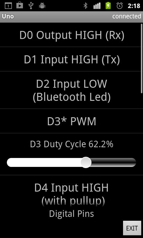
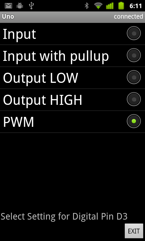
The final Digital Pin example is driving the Led with a PWM signal. PWM (pulse width modulation, see http://arduino.cc/en/Tutorial/PWM) turns the output on and off about 500 times a second. In each cycle of On and Off the percentage of time the Led is ON can be set by a slider on the mobile.
Click on D3 and from the configuration screen choose PWM. Only those Digital Pins marked with * have PWM capabilities. When PWM is selected a slider is displayed which lets you select the percentage the Led is On during each cycle. There are about 500 cycles per sec which is to fast for you to see each on/off switch. Your eye averages the result, so as you increase the % on time (the duty cycle), the Led appears to be brighter.
The AtoD inputs allow you to measure a voltage. The voltage applied to the AtoD input MUST NOT be greater the 5V. The AtoD compares the voltage on its input pin to the reference voltage and returns a number between 0 and 1023, where 1023 corresponds to the Reference voltage supplied to the AtoD. There are 3 reference voltages available, 5V, 1.1V and the voltage applied to the AREF pin. The 1.1V reference is not very accurate if you want to use it you will need to calibrate the result using a voltmeter. The 5V reference is accurate within a couple of %. If you want to use AREF you need to set up the reference voltage using the “Set AREF Analog Ref Volts” menu item, as well as connecting a reference voltage to the AREF pin.
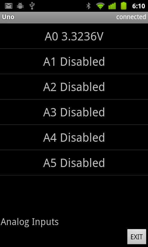
To measure a voltage, open the Analog Pin screen and click A0 to open its configuration screen. Choose the 5V reference. Then connect a 330ohm resistor between A0 and the 3.3V pin on the next header. The Analog screen will now show the measured volts. The pfodApp on your mobile re-request this screen about once a second.
The measurement will not be exactly 3.3V because of in accuracies in both the 5V reference and the voltage on the 3.3V pin and the electrical noise on the A0 pin.
One of the features of the pfod message specification is that when displaying a number in a menu, you can tell the pfodApp the apply a scale and offset as well as a units. When the 5V reference is selected and the UnoStarter sketch sends the Analog menu to the pfodApp on your mobile, it includes a units of “ V” and a scale factor of 0.0048876. When the AtoD converts the 3.3V input using a 5V reference, it will return a reading of 681 (681/1023 == 3.3/5). On your mobile the 681 counts is multiplied by the scale factor 0.0048876 = 3.328, so mobile will display 3.328 plus the units “ V”.
As well as setting the Digital I/O and enabling the AtoD inputs, you can also plot the values. About once per sec, the Uno pfodDevice sends raw data messages to the pfodApp containing the latest readings of the digital pins and the reading of the AtoD inputs, if enabled. You can view these reading via the Raw Data screen (accessed from your mobile's menu button).
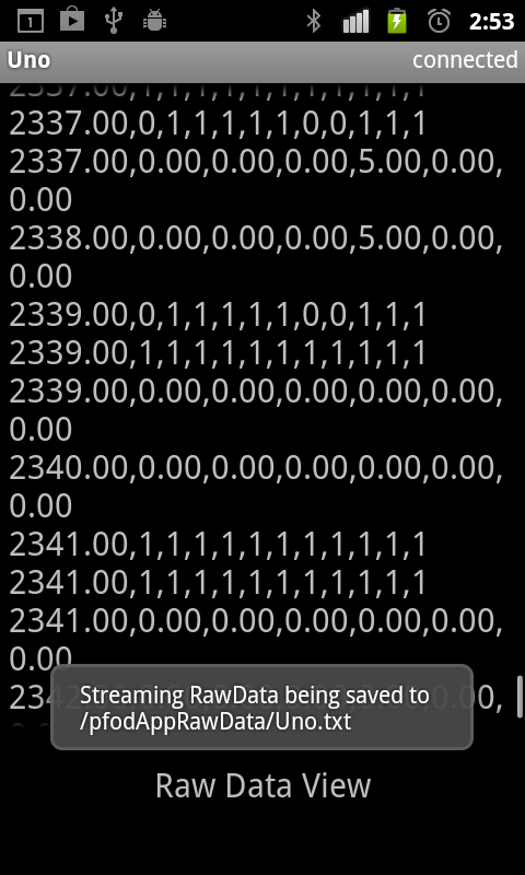
The
pfodApp automatically starts saving this data to a file on your
mobile when you view of plot raw data. You can later download this
file to your computer (see the pfodAppForAndroidGettingStarted.pdf
for the details).
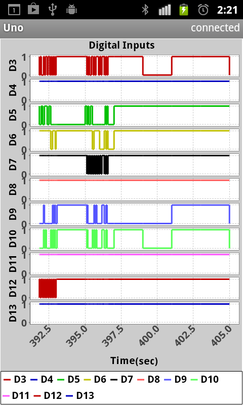
The Arduino code running on the Uno also provides two menu items to plot the raw data.
Choose “Plot Digital Inputs” to see the state of the digital pins. If set as an input the plot will update on each transition. If set as an output it will show the current state (high/low). If the digital pin is set as a PWM output then the plot will just sample the pin once per sec. Try connecting a pin set as PWM output to one of the other pins set as an input. The plot for the input pin will rapidly change as the it driven by the PWM output.
To see a plot of an Analog input you have to first enable one of the inputs, then connect a voltage to it. Try setting A3 with a 5V reference and then connecting a PWM digital output to it (twist 2 resistors together to bridge across the board). The sketch will sample the analog input once a sec and return the values for plotting.
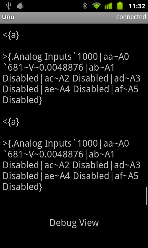
To see the messages that are being sent back and forth between the pfodApp on you mobile and the pfodDevice (your Uno), open the Debug View from your mobile's menu. Below is are the messages for the 3.3V measurement on A0.
< are message from the mobile to the Uno and
>
are messages from the Uno to the mobile.
The {a} from pfodApp requests the
Analog pins screen. The pfodDevice, the UnoStarter sketch responds
with the data for this menu.
The {. at the start of the message
specifies a menu screen. The “Analog Inputs” is the title
of the screen. The '1000 says re-request this menu again after 1 sec
(1000mS).
The | starts a menu item. The “aa” is the
command associated with this menu item and the text after the ~ is
the text to display. There are a number of versions of the menu item
from plain text e.g. “A2 Disabled” to scaled results with
units as in “A0`681~ V~0.0048876” to slider menu items.
See the pfod Specification
for all the details and examples.
To learn more about coding Arduino
see http://arduino.cc/en/Tutorial/HomePage
For more pfodDevice projects, like Android controlled garage door
openers, see www.pfod.com.au
If you want to continue with controlling things with Arduino you
will want to either purchase a
bread board and base
or preferably learn
to solder.
The following page will cover a simple example you can use as a basis for your own projects. No Android programming needed. Also check out Single Click Control of an on/off device.
You can also check out the pfod
Specification and the various projects on www.pfod.com.au
AndroidTM is a trademark of Google Inc. For use of the Arduino name see http://arduino.cc/en/Main/FAQ
The General Purpose Android/Arduino Control App.
pfodDevice™ and pfodApp™ are trade marks of Forward Computing and Control Pty. Ltd.

Contact Forward Computing and Control by
©Copyright 1996-2020 Forward Computing and Control Pty. Ltd.
ACN 003 669 994