
|
Home
| pfodApps/pfodDevices
| WebStringTemplates
| Java/J2EE
| Unix
| Torches
| Superannuation
|
| About
Us
|
|
|
High Frequency, Long Duration Datalogging
|
by Matthew Ford 21st June 2019 (originally
posted 21st June 2019)
© Forward Computing and
Control Pty. Ltd. NSW Australia
All rights reserved.
This project is a work in progress. The aim is to be able to log two ADC samples at 1000 samples/sec (i.e. 2K samples/sec total) continuously over 30 days. The current version uses an Arduino UNO, Adafruit Micro-SD breakout module, a quality 16G SDHC class 10 SD card and a communications module (WiFi, Bluetooth or BLE) to log the data.
There is also a 'faster' version of this project using a Teensy 3.2 with remote bluetooth control.
Arduino
UNO or compatible e.g. Adafruit
Metro Mini 328 - Arduino-Compatible - 5V 16MHz
Adafruit
MicroSD card breakout board+ or similar.
16G
SDHC class 10 MicroSD card of good quality.
6V or 9V power
pack e.g. https://www.sparkfun.com/products/15314
OR a 5V USB supply.
A led with a 470R resister in series.
A
communications module – e.g. one of the modules described on
Arduino
UNO/Mega Starter, controlled by Android/pfodApp
Download and install Arduino IDE V1.8.9+ from http://arduino.cc/en/Main/Software. That web page has links for various operating systems and a link to GettingStarted (http://arduino.cc/en/Guide/HomePage). Go through the GettingStarted steps for your operating system at the end of which you will have uploaded the BLINK program to your Arduino Uno board.
Download and install the following libraries :-
millisDelay
and SdFat
(A local snapshot of the SdFat library used for these tests is
here.)
Download the
library zip files and then use the Arduino IDE → Sketch →
Include Library → Add .ZIP library menu to install the libraries
from the zip files.
Unzip the UnoAnalogLogger.zip file to your Arduino sketches directory and program the Uno board with UnoAnalogLogger.ino
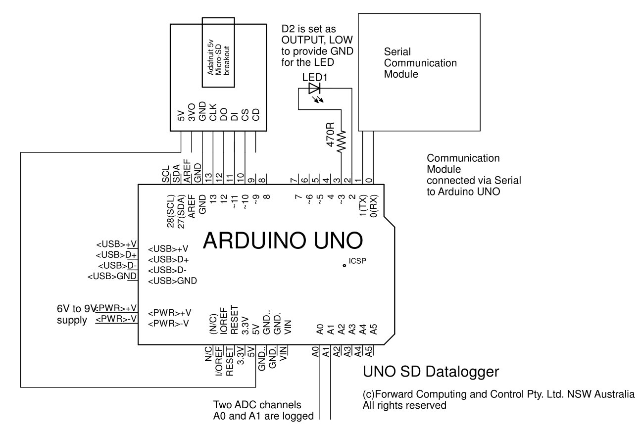
Wire up the Uno and the SD card module as shown below (pdf version)
To format the SD card use the https://www.sdcard.org/downloads/formatter/ The SD card must be empty in order to start logging.
For initial testing you do not need to connect the Communications module, just connect the UNO + SD module (with card installed) to the Arduino IDE via the USB serial cable.
Open the Arduino IDE Serial Monitor at 115200 baud. That will reset the UNO and after a few secs will display a menu of commands
? - current status
i - initialize files
c - convert file to csv
f - current file
o - open file
a - open all files (for use with e)
d - dump data to Serial
l - list files
e - missed samples error details
r - record ADC data
m - display Meta data
>
With an empty SD card, use the 'i' cmd to initialise the 99 files
used to store the data. Pre-initializing them here prevents loss of
data samples when switching from one file to the next.
You can
then use the 'r' cmd to start a logging run. The run will continue
until all the files are filled. This will take about 100*9.7hrs =
40days. The run can be stopped by entering the character s
The line
#define FILE_COUNT 99
near
the top of the sketch sets the number of files.
After the logging run has stopped, you can use the 'a' cmd to select all files and then the 'e' command to check for missing samples in all files.
The data is stored in the files in binary without any timing data. Each sample is assumed to be 1mS after the previous. A file can be exported as CSV by using the 'o' cmd to open the file and then the 'c' command to saved it as a CSV file. You can use the 'd' cmd to dump the CSV data directly to the terminal window.
The LED connected to D3 (with D2 providing the GND connection) will turn on solid if any sample is missed and will flash if there is an error. The sketch attempts to continue after errors but may not do so successfully.
Once you have tested the sketch you can try logging real data. Some points to note:-
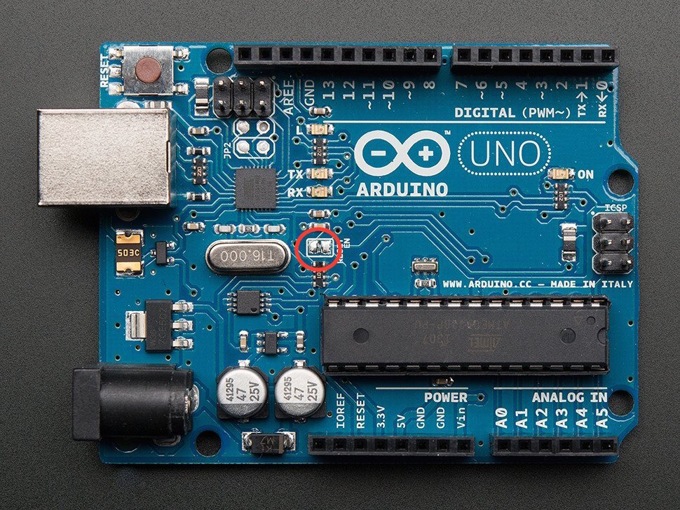
The UNO restarts whenever the USB opens a connection. To avoid this stopping your logging you should a) not use the USB cable, b) cut the Reset DTR connection on the Uno board as shown above (http://i.imgur.com/UeJSGWg.png) Once this link is cut is almost impossible to re-program the UNO so if you need to re-program it, either short the link out or add a switch between the two pads.
Use a stable power supply. Either power the UNO from a 6V to 9V supply via the plug jack OR wire a 5V USB supply to 5V / GND pins. Remember to remove the supply when re-programming the UNO
Use a communications module to start and stop the logging. The WiFi and Bluetooth modules on Arduino UNO/Mega Starter, controlled by Android/pfodApp can connect to a PC. For the WiFi open a Terminal Window and connect to the IP / port address you have set for the WiFi module. For the Bluetooth module, register it with your PC and then open a terminal window to that COM port. For the BLE module you will need a BLE terminal app such as nRF UART V2
So far a run using
#define FILE_COUNT 3
has
been completed taking about 27hrs. Checking for missing samples gave.
….
97% 96560386 samples  26:49:20:
98% 96885506 samples  26:54:45:
99% 97210626 samples  27:00:10:
No errors found in 767997 buffers
Longer testing is still to be done.
Due to the timing in-accuracies of the UNO processor clock, you can expect the duration of the run to be in error by some tens of seconds over a month.
The UnoAnalogLogger is a slight modification of Bill Greiman's AnalogBinLogger example in his SdFat Arduino library. AnalogBinLogger uses a pre-allocated and erased SD file and special block writes to minimize the SD latency. The SD writes are blocking and called from the main loop(). AnalogBinLogger uses the ADC conversion interrupt to pickup the sample value in an interrupt handler and save it of a 512byte buffer. The buffer is written to the SD card when it is full.
On the UNO, which has limited RAM available, AnalogBinLogger only uses two buffers one of which is recycled from the SdFat vol.cache buffer. In UnoAnalogLogger multiple (99) files pre-initialized before the logging is started and then opened and closed as it progresses, so the vol.cache is not available for to use to buffer the samples. This means there is only one buffer available, however in the run tests the max latency for an SD buffer write was 750uS (i.e. <1mS) and no samples were lost.
The same code should also be able to be run without change on an Arduino Mega2560 which has 4 times as much RAM and will allocate more buffers. This should allow for higher sampling rates or more ADC samples.
Both the UNO and Mega2560 boards use AVR 8 bit micro-processors. Other non-AVR Arduino boards have micro-processors that also support ADC conversion completed interrupts and so should also be able to use similar techniques to perform high speed long duration sampling.
For use of the Arduino name see http://arduino.cc/en/Main/FAQ
The General Purpose Android/Arduino Control App.
pfodDevice™ and pfodApp™ are trade marks of Forward Computing and Control Pty. Ltd.

Contact Forward Computing and Control by
©Copyright 1996-2020 Forward Computing and Control Pty. Ltd.
ACN 003 669 994