
|
Home
| pfodApps/pfodDevices
| WebStringTemplates
| Java/J2EE
| Unix
| Torches
| Superannuation
|
| About
Us
|
|
|
Discretionary Load Control on an |

This a short description of how Simon used pfodApp to control discretionary loads on his Off the Grid Power System
My wife and I live off the electricity grid on a small rural property. Our off grid system is an AC coupled Photovoltaic (PV) system that uses a combination of Sunny Boy inverters (PV to 240V 50 Hz) and SMA Sunny Island inverter chargers (48Vdc battery to 240V 50Hz bidirectional). The Sunny Boy inverters are set up with a droop function on their power output that reduces its power output as the mains frequency rises (100% output at 51Hz dropping to 0% output at 52Hz). The Sunny Island inverter chargers charge and discharge the batteries as required to maintain the mains voltage.
When there is more power from the PV panels than we use, the Sunny Islands charge the batteries. If the batteries are close to full and there is excess PV power, the Sunny Islands can't dump all the excess power into the batteries and act to limit the output of the Sunny Boys by raising the mains frequency. SMA calls this Frequency Shift Power Control (see SB-OffGrid-TI-en-42.pdf).
Using the grid frequency as an indicator of excess power being available from our PV panels, I wanted to automatically control discretionary loads such as water pumps and pool filters around our house.
Our power system is remote from our house so the control panel is not convenient to access and monitor. There are expensive proprietary products I could use to control the discretionary loads, but they would also require additional cables to be run from the power system to the house however for less than $150 of parts I used an Arduino to measure the mains frequency and some radio controlled switches to switch the loads.
The Arduino counts the mains frequency pulses from a 240V/9V transformer and calculates a rolling average over 25sec to measure frequency to an accuracy of 0.02Hz. A 433MHz transmitter is used to control off the shelf radio controlled switches (Watts Clever Easy Off Sockets) that are used to switch the discretionary loads.
The user interface is provided on an Android phone using pfodApp via a Bluetooth connection.
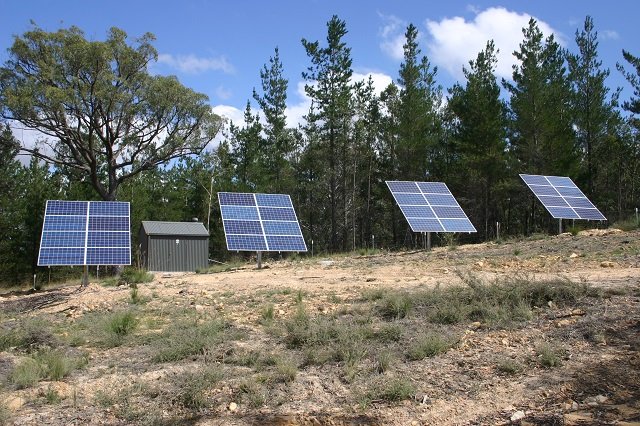
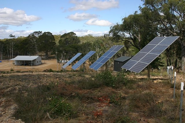
These are four (4) independent solar arrays of 2kW each. The mounts do not track although they can have the angle changed from horizontal to 60 deg. They are currently at 40 deg and we have excess generation. They could be raised to 60 deg during winter to improve output if necessary. Behind the array second from the left is the equipment room where the batteries and inverters are housed. At the rear of the equipment room there is a small lean-to which covers a 5.5kVA backup petrol generator.

This shows the inside of the equipment room. The red devices are the Sunny Boy inverters rated at 4kW each (each served by two of the solar arrays) and the yellow devices are the Sunny Island inverters rated at 4600W continuous. On the right you can see the batteries. These are 2V 1200Ahr lead acid cells in a 48V pack. Everything is automatically controlled by the Sunny Island inverters including paralleling and loading the backup generator in the event of low batteries or excessive load.
Above is the block diagram of the Frequency
Controlled Switch system.
This
photo shows the controller in its enclosure and the power supply.
Conveniently the power supply supplies both the 6.5Vdc used to power
the Arduino and the 9Vac which the Arduino counts.

This is a closer view of the controller hardware The major components visible are the protoshield (left) that was used to assemble all the additional components to the Arduino, the 433MHz transmitter (top right) and Bluetooth module (bottom right).
The Arduino is under the protoshield. The discrete components on the protoshield (two diodes and a resistor) are used to clip the 9Vac waveform so it approximates a square wave which is used to trigger an interrupt on the Arduino to increment the appropriate counters.
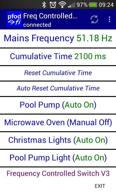
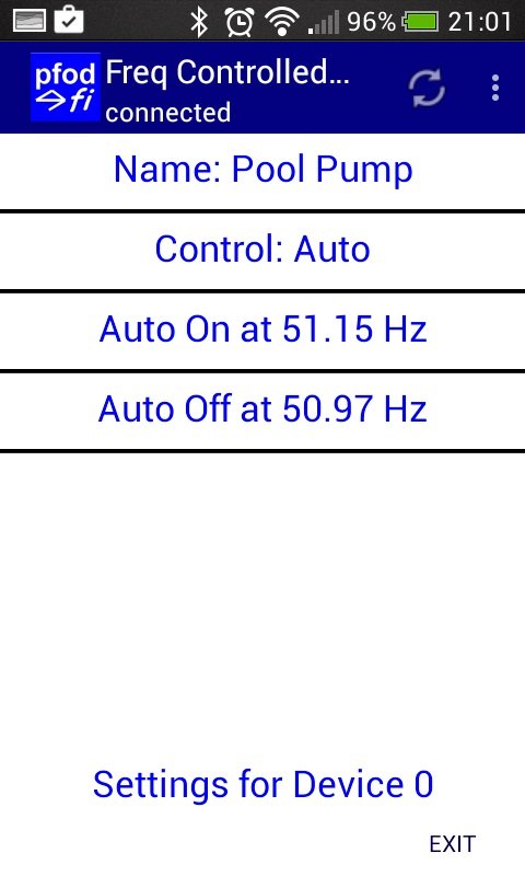
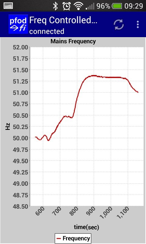
Here is the pfodApp main menu and one of the sub-menus that controls the individual switches. pfodApp can also plot the frequency over the last 10min period.
The
complete code is not provided but you can generate the Arduino code
for the menus/sub-menus and on/off buttons and the chart using
pfodDesignerV2.
The frequency is measured using an interrupt routine and a rolling
average. The code
measuring the frequency is here.
Next part of the project is to add infra red control to control the air conditioner as well. Update 7th July 2016, from Simon “My initial aim was to only pump water to the header tank when there was excess energy but as we appear to have a significant excess on some days we have taken to running the reverse cycle air conditioner to heat the house in the afternoon – it saves me having to chop wood for the fire.”
AndroidTM is a trademark of Google Inc, For use of the Arduino name see http://arduino.cc/en/Main/FAQ
Matthew Ford 1st March 2016
©
Forward Computing and Control Pty. Ltd. NSW Australia
All rights
reserved.
The General Purpose Android/Arduino Control App.
pfodDevice™ and pfodApp™ are trade marks of Forward Computing and Control Pty. Ltd.

Contact Forward Computing and Control by
©Copyright 1996-2020 Forward Computing and Control Pty. Ltd.
ACN 003 669 994