
|
Home
| pfodApps/pfodDevices
| WebStringTemplates
| Java/J2EE
| Unix
| Torches
| Superannuation
|
| About
Us
|
|
|
Home Automation
|
by Matthew Ford 1st July 2015 (originally
posted 10th September 2014)
© Forward Computing
and Control Pty. Ltd. NSW Australia
All rights reserved.

This pfodApp (Android) controlled Dual Power Switch is a project for experienced constructors and as such does not cover every detail of the construction.
Works with 110V to 240V and can be adapted to US, EU, UK etc. by changing the plugs and sockets on the flying mains leads
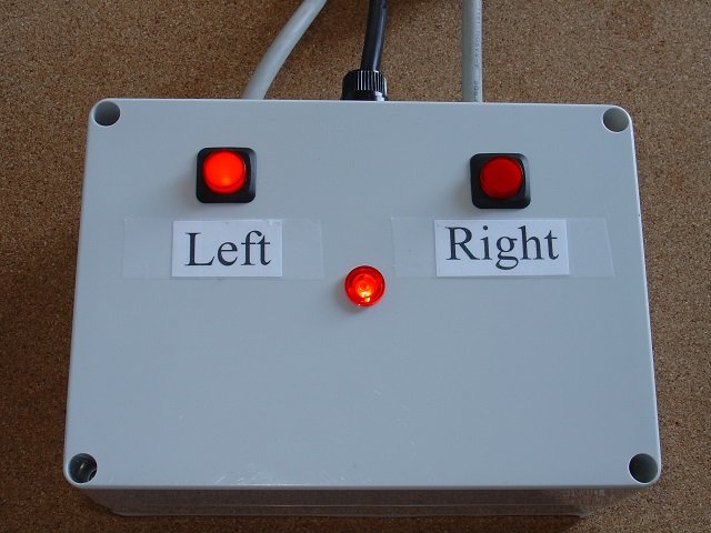
Has manual push button control in addition to control over WiFi/Internet, via pfodApp running on an Android mobile.
Has push button configuration, using pfodWifiConfigV1, of network parameters (ssid and password) as well as setting the device's IP and listening port No.
Includes 128bit security to protect again un-authorized operation.
Remembers the switch settings on loss of power and powers up in its previous state.
Indicator Leds and pfodApp monitor power on the output mains lead, not the drive to the relays. That is, if the relay fails to operate or welds closed, the Leds and pfodApp reflect the present of power on the output mains leads.
This parts list is only an indication of the parts used in the project.
Arduino Compatible with WiFi – This project use FioV3 and a WiFly Xbee form factor plug in for the WiFi.
USB power supply – In this project the power board was removed from the USB supply case and mounted on stand-offs
Dual mains power relay board, opto-isolated, 5V drive – The FioV3 is a 3.3V board so a second 10K resistors was put in parallel with the resistors on the relay board driving the opto input. (see Modifications for Driving a 5V relay module from a 3.3V Arduino board)
1 off Mains Power cable with plug
2 off Mains Power cables with sockets
2 off 6N139 optical isolators – This project used 6N138 optical isolators (see Output Power Monitoring below)
2 off 1N4004 diodes – To protect the 6n138's from reverse voltage
1 off power neon
2 off push-buttons with integral leds
1 off fuse holder and 10A fuse
2 off 130ohm resistors
2 off 240K resistor (see text below)
Misc Hardware – Insulated box, veroboard, mounting screws and stand offs, header pins plugs and sockets, 4 way power terminal strip.
pfodApp – An Andriod app for your mobile which can monitor and can control the power switches securely via WiFi/Internet.
pfodWifiConfigV1 – A free Android app to configure the Dual Power Switch for your network.
pfodDesigner – A free Android app to let you design your own menu for the Dual Power Switch.

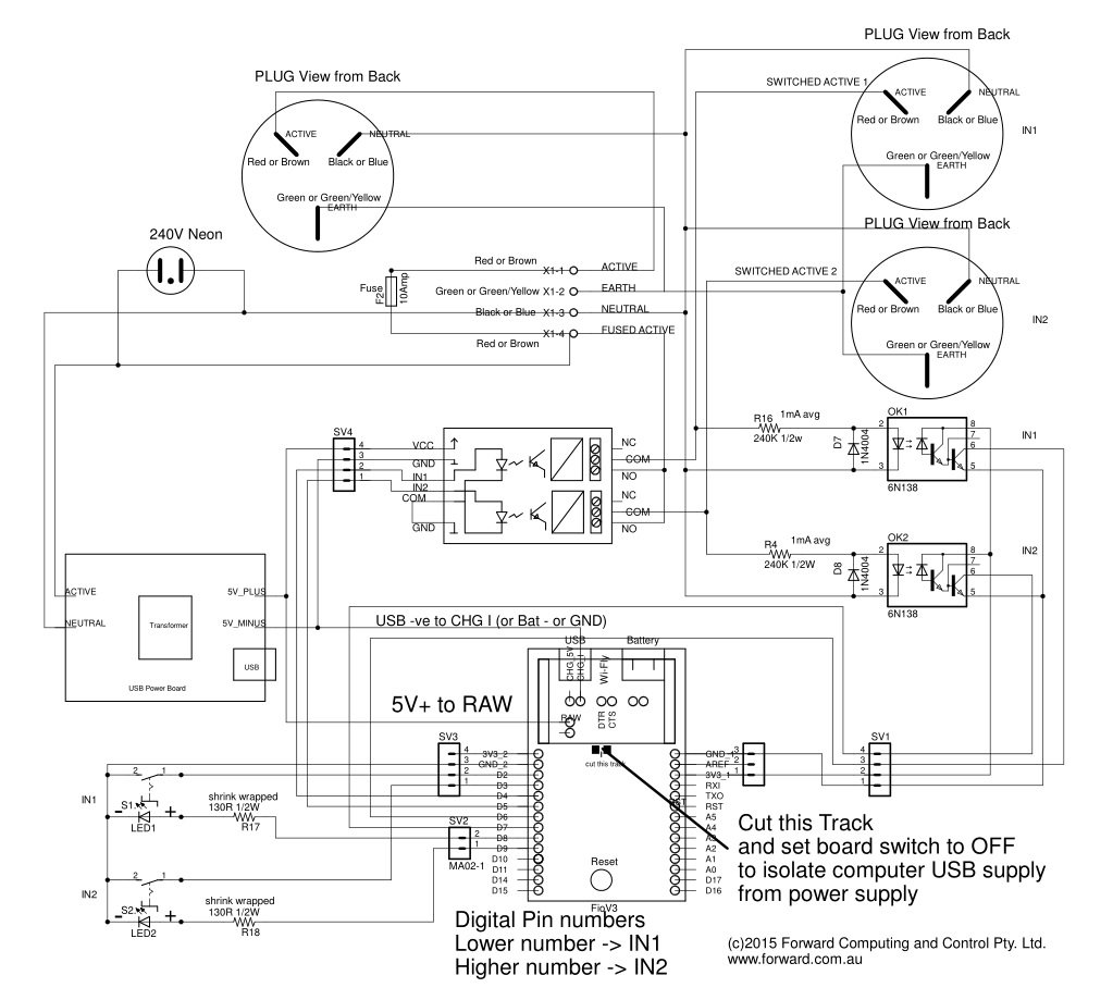
The circuit diagram is available as a pdf here.
This is a project for experienced constructors who can follow the circuit diagram and the general layout pictured above. However here are a few notes on some of the design and construction choices made.
Safety – A fully insulated polycarbonate box was used. No metal projects from the inside to the outside of the box. The push-buttons, neon indicator and fuse holder are all plastic. The screws for the lid are external to the where the circuit is mounted and the veroboard is screwed down in internal mounting points. The avoids the need for box/circuit earthing. If any mains wiring does come loose inside it is completely contained within the box. Care has also been take to put shrink rap on all mains terminals and to put a plastic barrier over the USB power board so that the project is reasonably safe for programming with the lid open, provided you don't stick you finger down onto the 6N138 opto pins.
Fuse Holder – It is possible to undo the fuse holder and access a live mains voltage that way. If there are small children around you should delete the fuse holder and mount the fuse inside on the veroboard.
Push Button Led Resistor – The 130ohm resistors in series with the push-button leds are mounted on the push-button terminal and enclosed in shrink wrap (red). This value was chosen for about 10mA from the FioV3's 3.3V drive
FioV3 Power Supply – The FioV3 is powered from the USB power board connected to it RAW input. To prevent this supply fighting with the computer's USB supply when programming the FioV3, the FioV3 board mounted power switch was set to off, as shown in the photo below, and the supply track was cut as indicated on the schematic and in the photo below.

Output Power Monitoring – As mentioned above the mains power on the output leads is monitored and displayed by the push-button leds and the pfodApp screen. This is done via the 6N138 opto isolators. In the first iteration of this project, the push button leds and the optos were in series and driven directly from the 240V output via a capacitor/resistor full wave rectifier combination. (see this pdf for examples (Microchip AN954)).
However that solution did not last long. The resistor bunt up and the led failed. So for the second iteration, the opto isolator was driven from the 240V via a current limiting resistor and the push-button leds are now driven by the FioV3 based on the output of the opto isolators. See the sketch for more details.
Initially a 470K ohm resistor was used but 0.5mA or so that it provided was not sufficient to reliably drive the 6N138 opto. So the resistor was halved to 240K ohms for 240V supply (110K ohms for 110V). This dissipates about ~0.25W per opto. If you can use the more sensitive 6N139 opto's then try the 470K resistor for 240V supply (240K ohms for 110V), which reduces the power dissipated by the resistor to ~0.125W per opto.
Access to Program the FioV3 – The FioV3 board is mounted on high stand-offs so that is USB programming port is accessible by just talking the lid off the box.
The complete sketch, pfodSwitchPower_FioV3_WiFi.ino, is available here. The basic sketch was created using pfodDesignerV2 and then modified to add the pfodWifiConfigV1 code, 128bit security, button debounce and EEPROM storage of the switches' states.
To compile this sketch you need to
add a number of libraries to your Arduino IDE:-
DebounceSwitch
– to handle the pushbuttons.
pfodWifiConfigV1
and pfodWifiConfig_WiFly – to provide the push-button
configuration.
pfodParser
– to provide pfodSecurity for the 128bit Internet security.
Start by preparing your own pfodWifiConfigV1 QR code containing your own temporary access point password. The example sketch uses this QR code
 You
should generate your own code and update the sketch with your
password.
You
should generate your own code and update the sketch with your
password.
//
update this define with the password from your QR code
//
http://www.forward.com.au/pfod/pfodWifiConfig/pfodQRpsk.html

#define
pfodWifiConfigPASSWORD "plyWtEDk6uZ0yfmAEM5wMc"

//
the ssid is "pfodWifiConfigV1" and the port is 23 -- set by
pfodQRpsk program
The ssid and password contained in this generated QR code is the one the WiFly module will use, in config mode, to connect to the temporary access point in order to be configured. The pfodWifiConfigPASSWORD is also used as the 128bit Internet security password to prevent un-authorized access to this device. This password QR code also needs to be scanned into the pfodApp connection.
Two points about the pfodSwitchPower_FioV3_WiFi.ino sketch:-
On start up (when power is applied), the sketch checks to see if both push-buttons are pressed. If so it flashes them both for 10secs to indicate it is in config mode and then starts the pfodWifiConfigV1 config mode.
The opto-coupliers that monitor the output power on each lead are only driven for less then half an AC cycle. At the start and end of the positive AC power cycle there is not enough voltage to drive the opto-coupler and in the negative AC cycle the diode by passes the opto-coupler. The sketch handles this by resetting a timer each time the opto-coupler fires and only times out if there have been no pulses for POWER_CYCLE_LENGTH (20mS) milliseconds. This keeps the push-button leds lit and the pfodApp display constant while ever power is available to the output lead.
Complete the construction by attaching the pfodWifiConfigV1 QR code and instructions for configuration to the back of the Dual Power Switch. These instructions are available as an Open Office file here.
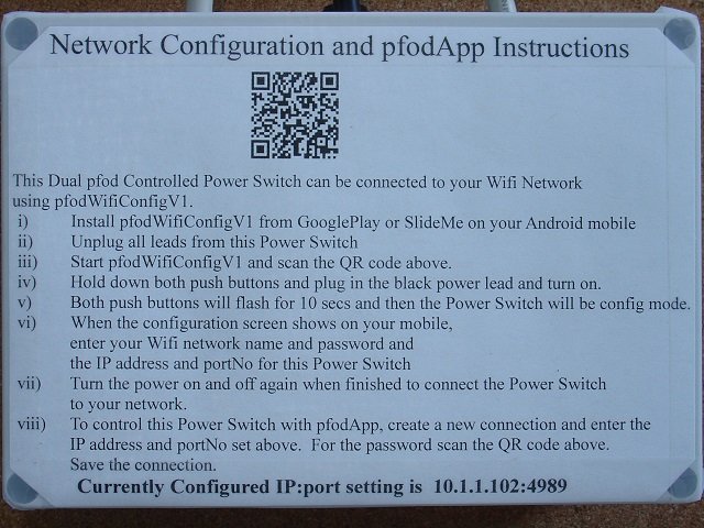
Once the FioV3 has been programmed with the pfodSwitchPower_FioV3_WiFi.ino sketch, you can configure its WiFi parameters and DHCP/StaticIP and server portNo via pfodWifiConfigV1.
To do this first install the free Android app pfodWifiConfigV1 from Google Play. If you don't have Google Play on your mobile you can install the app from SlideMe. If you don't have an Andoid mobile you can still do the configuration from a computer using Telnet.
Then start the pfodWifiConfigV1 app.

Then
press the Scan QR Code button and scan the QR code attached to the
Dual Power Switch. This code is used to open an Access Point on your
mobile.
NOTE: Some network providers
attempt to prevent you creating an Access Point on your mobile,
depending on your contract. If the pfodWifiConfigV1 app cannot create
an Access Point on your mobile you will have to use the Telnet
option to configure your device.
Now
with the power off, press both push buttons on the Dual Power Switch
and turn the power on. Both push buttons will flash for 10 seconds
indicating it is in config mode. When the flashing stops the WiFly
will try and connect to your mobile access point.
(Note: if the FioV3 USB cable is
plugged into the computer the start of the flashing is delayed for
about 10sec while the USB connection sorts itself out.)
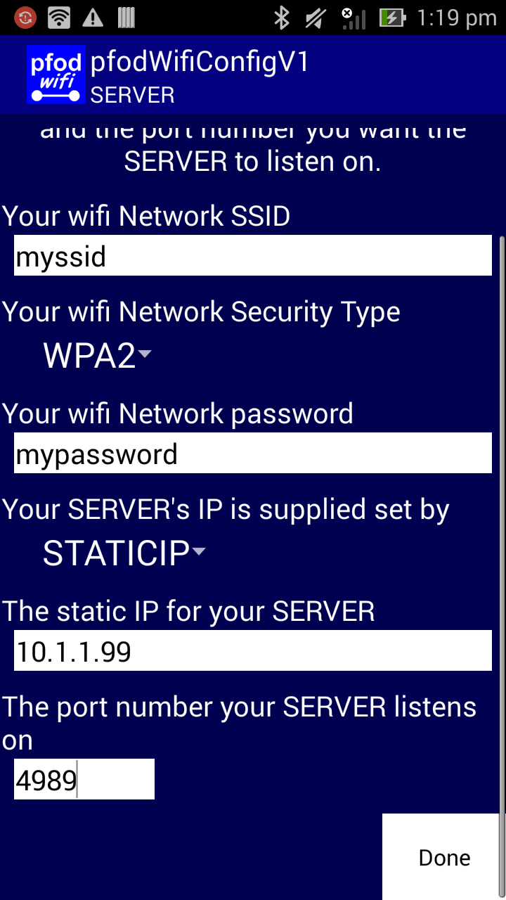
When the Dual Power Switch connects to your mobile's temporary Access Point, the pfodWifiConfigV1 displays the available configurations as defined in the sketch. In this case the available configuration is as a server with either DHCP or StaticIP and portNo for the server to listen on.

If
you want to use DHCP, click the STATICIP drop down and change it to
DHCP.
Here is an example filled in with dummy data. (As shown on the Dual Power Switch instructions above, this unit is actually setup on 10.1.1.102:4984 )
Clicking
“Done” sends the data to the Dual Power Switch to be
saved in EEPROM, and displays the following screen.

Note
the simple text message sent to the ESP8266
{set
myssid WPA2 mypassword 4989 10.1.1.99 }
If you were using telnet to configure the module, this is the type of message you would send. See the pfodWifiConfigV1 protocol definition for the format of the {set commands.
Then power cycle the Dual Power Switch and it will connect to your local network and start listening on 10.1.1.99:4989 for pfodApp connections. As shown on the Dual Power Switch instructions above, this unit is actually setup on 10.1.1.102:4984.
Finally install pfodApp and set up a connection to the Dual Power Switch (see pfodAppForAndroidGettingStarted.pdf for the details). This connection is secured by the same password used for pfodWifiConfig. To enter that password into your connection use the Scan QR button on the pfodApp connection screen and scan the pfodWifiConfig QR code. Next time this screen is opened the password will be *hidden*

Then
connect to the Dual Power Switch
When
you manually press one of the push buttons (push on/ push off), the
pfodApp screen updates with the current switch setting. You can also
turn the outputs on and off from the pfodApp by clicking any where in
the button area. The pfodApp re-requests the current state of the
switches once a second.
If you open the Debug View from the pfodApp menu, you will see the secure hash hand shake at the start of the connection and the hash added to each message. This prevents un-authorized access by anyone who does not have the password. The connection is dropped by the Dual Power Switch is any of these hashes are invalid.

After
30secs in Debug View, the connection will be dropped because the
pfodApp has stopped re-requesting the switch state. This prevents
some one denying you access to the Dual Power Switch by just
connecting to the host and port and not sending any messages.
This Dual Power Switch is a project for constructors experienced in mains power. It proves 128bit security for WiFi/Internet access to control two mains power switches. Manual operation is also available at the unit. The leds in the push-buttons monitor the power in the output leads. Connecting this unit to your network and setting up its IP address and portNo are easily done using the free pfodWifiConfigV1 app.
AndroidTM is a trademark of Google Inc. For use of the Arduino name see http://arduino.cc/en/Main/FAQ
The General Purpose Android/Arduino Control App.
pfodDevice™ and pfodApp™ are trade marks of Forward Computing and Control Pty. Ltd.

Contact Forward Computing and Control by
©Copyright 1996-2020 Forward Computing and Control Pty. Ltd.
ACN 003 669 994