
|
Home
| pfodApps/pfodDevices
| WebStringTemplates
| Java/J2EE
| Unix
| Torches
| Superannuation
| CRPS Treatment
|
| About
Us
|

|
Android controlled Garage Door Remote
|
by Matthew Ford 20th May 2016 (original
21st July 2012)
© Forward Computing and Control
Pty. Ltd. NSW Australia
All rights reserved.

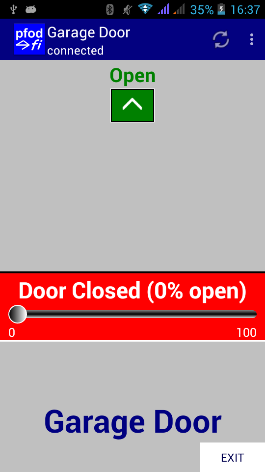


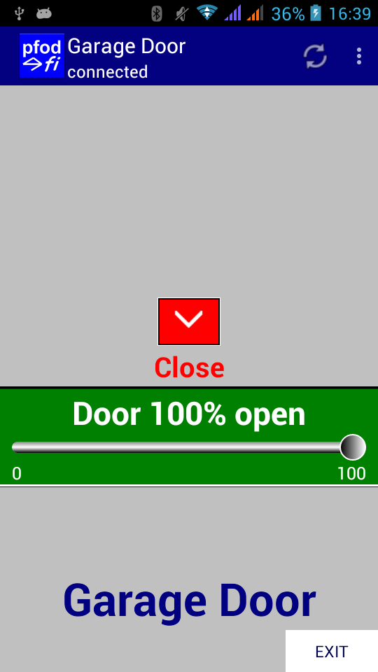
This Internet Garage Door opener uses an OLIMEX ESP8266 EVB module and an accelerometer to measure the position of the tilt-a-door and limit switches. The control over WiFi or Internet is via pfodApp. 128bit security is used to protect against un-authorized operation. Connection to the local WiFi network and configuration of the device's IP and portNo are via web page. No Android coding is required, the pfodApp takes care of all of that.
Rev 1 of the code with more reliable connection
and the push button operates as a manual push button as well.
Rev
2 includes a 2sec lock out on double presses of Open or Closed
buttons, but can always use Stop/Start button
Rev 3 auto
reconnects to WiFi network, ignores user input for Position slider.
(Needs V2.0.2 of pfodesp8266wifi.zip library)
Rev 4 updated to
work with ESP8266.com IDE plug-in V2.2.
(pfodESP8266BufferedClient.zip library)
Features:
Simple construction – One main board and small daughter board, one resistor and 6 wires
Simple to configure – Push button configuration of WiFi Network SSID and Password and device IP and PortNo
Simple to use – pfodApp provides the Android interface. No Android coding required
Secure – Uses 128bit security
Construction consists of two parts:- the control module and the installation of limit switches and door mounting and wiring.
The control model use an OLIMEX ESP8266 EVB module which has a build in relay. The relay is wired in parallel with the existing garage door pushbutton. When the code pulses the relay, the garage door operates. To detect the position of the door there are limit switches at each end of the door travel as well as an ADXL335 breakout board from SparkFun. The limit switches act as a backup for the position reading from the ADXL335.
Only one of the outputs from the ADXL335 is used. A 33k resistor to ground on that output reduces the signal level to less the 1.0V as required by the ESP8266 TOUT ADC input. Due to the variation in the ADXL335 specs, you may need to reduce this resistor to 27K.

The
schematic
is here as a pdf.
The following photos show the wiring of the control module.
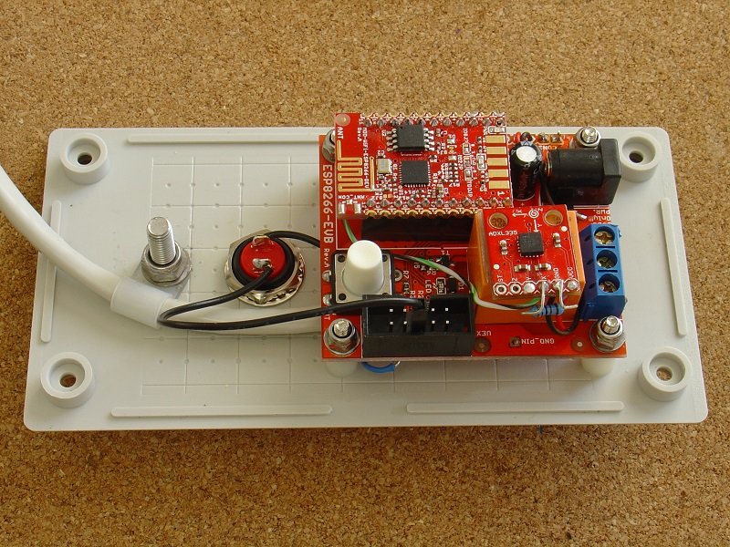
The ADXL335 break out board mounted on the OLIMEX relay with heavy duty double sided tape. The 33K resistor to ground is mounted directly on the break out board. The configuration push button is connected between GPIO2 and GPIO0 (See Using ESP8266 GPIO0/GPIO2/GPIO15 pins)
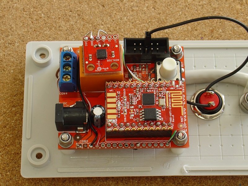
Cat 5 cable (8 way) is used to connect the control module to the 5V USB supply, 2 limit switches and garage door push button.
The wires used in this project where:-
Orange/White
for 5V (+5V orange)
Green/White for Close Limit Switch, normally
open (GPIO12, GND)
Blue/White for Open Limit Switch, normally open
(GPIO13, GND)
Brown/White for Relay output for Push Button contact
(in parallel, normally open)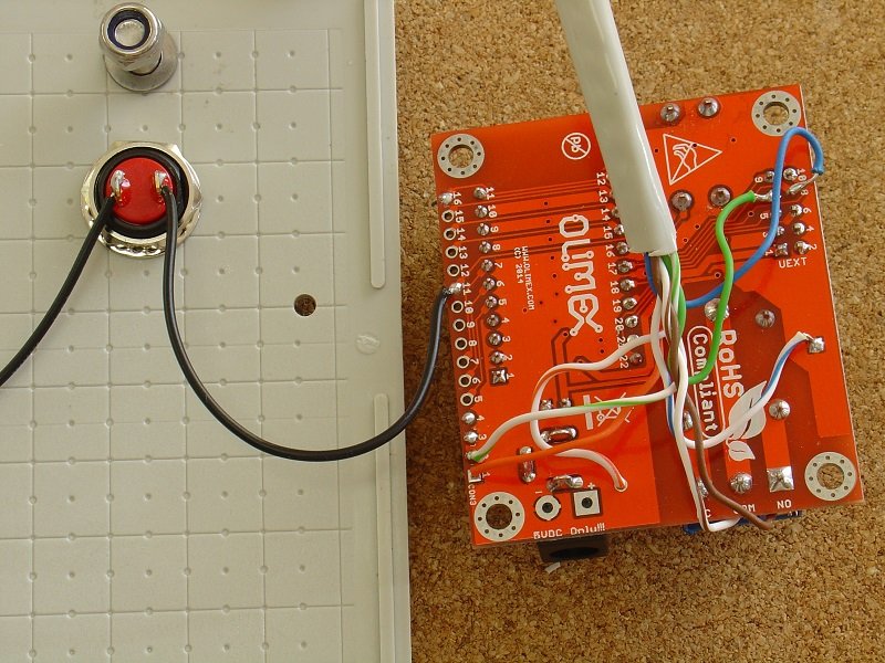
Sold core Cat 5 cable was used for the main wiring and stranded Cat 5 cable was use for the flexible connection to the control module.
The control module was installed on one of the rotating arms of the tilt-a-door, with stranded Cat 5 cable back to a terminal strip.

Solid core Cat 5 cable runs from this terminal strip
back to the terminal strip mounted on the tilt-a-door control
unit.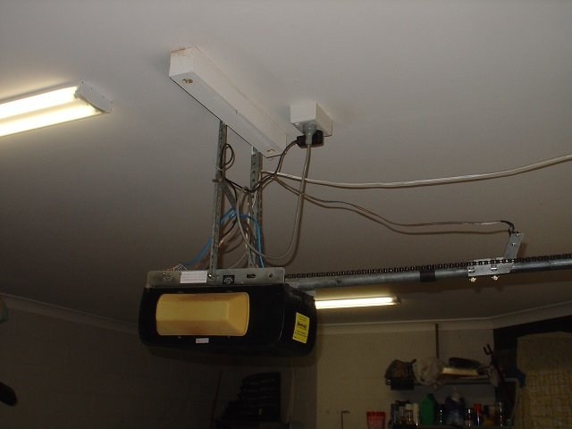
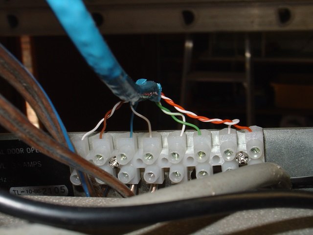
The
limit switches are mounted on each end of the tilt-a-door's central
rod.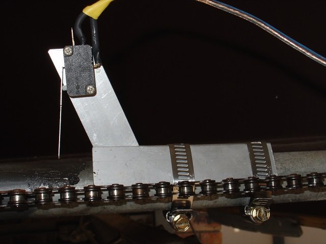
Once the control module is mounted, it needs to be calibrated to the movement of the arm. The calibration sketch is here, GarageDoorAngle.ino.
To load the sketch you will need a separate 5V supply for the OLIMEX module. See this page for details on programming the OLIMEX.
Modify the sketch to put in your network's ssid and password. The IP address is set as 10.1.1.110. You can change it in the setup() if you need to. The portNo is 4989
Load the sketch into the OLIMEX module. Secure the lid on the box attached to the door. The power it up and connect using pfodApp. There will be just one button available, “Plot the Angle”. Pressing this button will show a plot of the ADXL355 reading at 1 sec intervals. Open and close the door to get the range of readings.

The
reading are also saved to a file on your mobile.
In this case the filtered reading for OPENED was 1000 and the reading for CLOSED was 673. If they go the other way, mount the OLIMEX board the other way up. If the reading does not change much, use a different output from the ADXL355 board to get a larger range of change.
In addition to the analog filter on the output of the ADXL355, a digital filter was added in the code. This filter averages the last 32 readings to filter out noise and mechanical vibrations. The sampling interval is 10mS so this filter averages over the last 0.32Sec. Note: this filter is not the common exponential filtering. Exponential filtering uses less storage, just one floating point location, but requires a time consuming multiplication. But more importantly, a large spike in the input takes a long time to die away in an exponential filter. On the other hand the true averaging used here completely discards any spike from the calculation after 0.32 seconds. This was considered an essential feature because of the vibration observed at the end points of the door's travel.
In this setup the filtered reading for OPENED was 1000 and the reading for CLOSED was 673. So the values in the code were set at 995 to 678 (within 1.5% of open and closed) for 0% to 100%
When the CLOSED limit is operated the sketch will display the “OPEN” button. When the OPENED limit switch is operated the sketch will display the “CLOSE” button. The limit switches are a positive indication that the door has reached that position. Previous testing has shown that if the limit switches move they tend to move away from the door slider and so do not operate at all. If a limit switch wire drops off, the most likely fault, then again the limit switch will not be detected as operated. In either case the garage door position slider will just indicate the position of the door, 0% or 100%, and the pfodApp will just display the Start/Stop button, which will indicate this fault.
The pfodApp will display a navigation screen with a
slider below it. The Navigation buttons will be,
UpArrow for Open
– Only shown when the CLOSED limit switch is operated and the
OPENED limit is NOT operated.
DownArrow for Close – Only
shown when the OPENED limit switch is operated and the CLOSED limit
is NOT operated.
Home for STOP/START – Shown when neither
the up or down arrow is shown OR if both limit switches are operated.
See the screen shots at the top of the page.
As well as setting the end points for the position sensor, you need to generate your own 128bit configuration password. This password secures the temporary WiFi connection used to set your local network's real password. This same password is also used by pfodApp to protect against un-authorized access to the control of your garage door. You could set different passwords for these two functions but it is convenient to have just one QR code and use the same password for both.
To generate a random password and the associated QR code, a SecretKeyGenerator java program is available here which generates random 128bit keys and writes out QR.png files. Another alternative is to use QR Droid Private (from Google Play) to create a QR Code for your own chosen password.
Here is the OpenOffice
template that was used to print out the QR code and other
connection details for this project. Update it with your own QR code
and password.
In either case you need to update the #define near the top of the sketch with your own password.
// =============== start of pfodWifiWebConfig settings ==============
// update this define with the password from your QR code
//  http://www.forward.com.au/pfod/secureChallengeResponse/keyGenerator/index.html
#define pfodWifiWebConfigPASSWORD "b0Ux9akSiwKkwCtcnjTnpWp"
You can also set your own configuration Access Point name, if you wish.
The completed sketch is
GarageDoorWithPosition.ino.
See this page for details
on programming the OLIMEX. To compile the GarageDoorWithPosition
sketch you will need to install three (3) libraries. You need to
install pfodParser.zip and pfodESP8266BufferedClient.zip from here.
You also need to install the DeboucedSwitch.zip library from here.
You can then attach the QR code, containing this password, to you module or in some other suitable place, so you can re-configure the module when necessary and scan the password into pfodApp in-order to make a connection.
Once you have completed the final coding and installed the module, you can use the push button to enable configuration mode. Hold the push button down while applying power to the module. The module will set up its own WiFi access point, pfodWifiWebConfig, which will be visible on your mobile phone. Scan the QR code to get the password for this access point and paste it into you WiFi setup in order to connect your mobile to the module's configuration web server.
Then in your mobile's web browser, enter 10.1.1.1, to open the configuration web page.
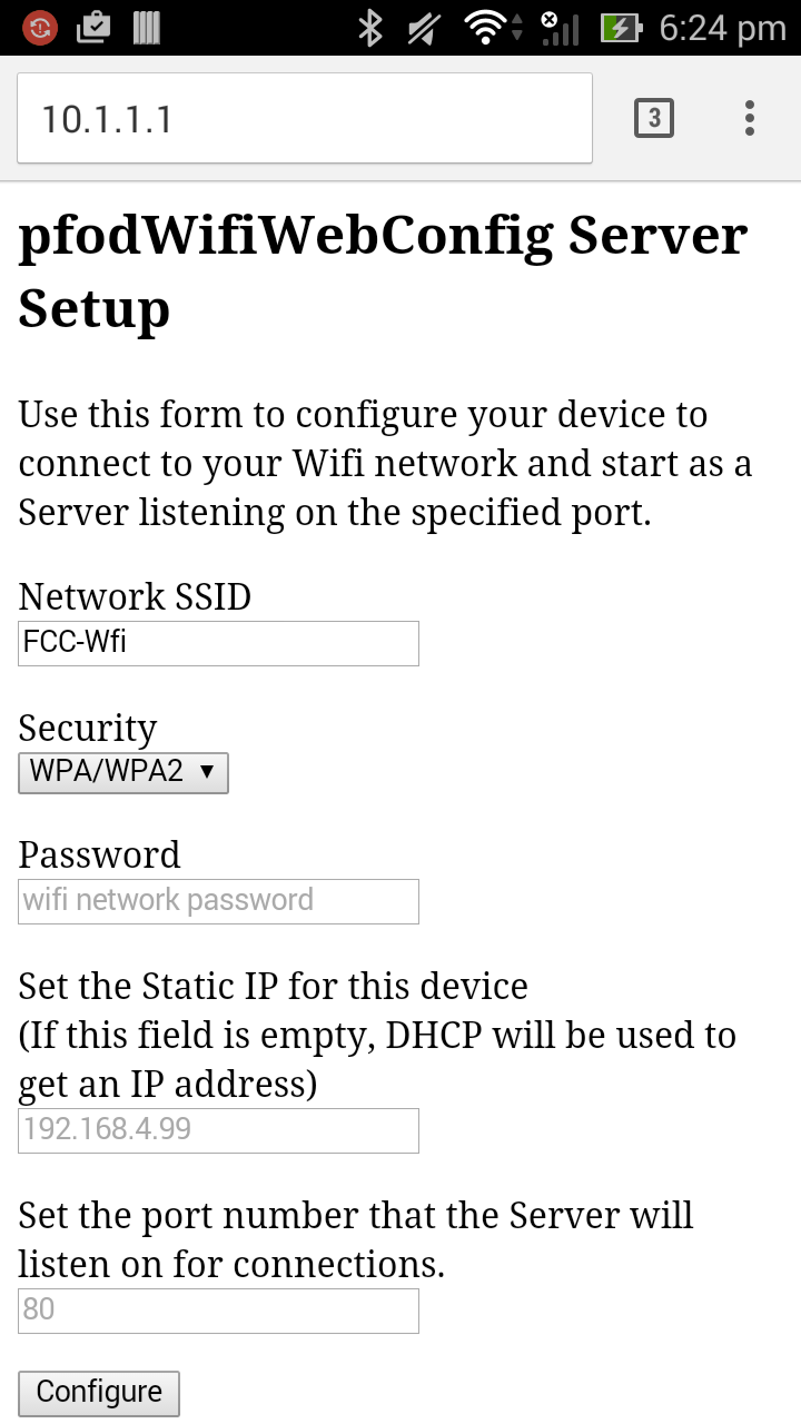
The
WiFi Shield automatically fills in the Network SSID with the local
network with the best signal strength. This will usually be the one
you want. If not just overwrite that entry. You must enter a Network
SSID and password and portNo. The IP address field is optional. If
you leave it blank, the WiFi Shield will use DHCP to get its IP
address on your local network. It is often easier to specify a
specific IP address so you can easily connect to the module.
Once you have connected the module to your network, you can set up a connection in pfodApp as described in pfodAppForAndroidGettingStarted.pdf. In the connection screen, click the Scan QR button and scan the code above to fill in the 128bit security password.

On
connecting you will see a screen like one those at the top of this
page.

Press
the OPEN button to open the door. You can stop the door mid way using
the Stop/Start button which is displayed as soon as the door moves
off the limit switch.
That's all there is to it.
AndroidTM is a trademark of Google Inc. For use of the Arduino name see http://arduino.cc/en/Main/FAQ
The General Purpose Android/Arduino Control App.
pfodDevice™ and pfodApp™ are trade marks of Forward Computing and Control Pty. Ltd.
Contact Forward Computing and Control by
©Copyright 1996-2024 Forward Computing and Control Pty. Ltd.
ACN 003 669 994