
|
Home
| pfodApps/pfodDevices
| WebStringTemplates
| Java/J2EE
| Unix
| Torches
| Superannuation
|
| About
Us
|
|
|
BluePill (SMT32) programming with Arduino
|
by Matthew Ford 20th Jan 2022
(originally posted 20th Jan 2022)
©
Forward Computing and Control Pty. Ltd. NSW Australia
All rights
reserved.

Contents
Parts List
Preparing
the “BluePill”
Preparing
the ST-Link V2
Installing the STM32 Arduino IDE
add on
Installing the SafeString Library for the
millisDelay class
Tools Menu
Settings
Programming with
STM32CubeProgrammer and ST-Link V2
Programming
via the HID bootloader
Programming via the
Maple bootloader
Installing
the Maple Drivers
Programming the
“BluePill” as a USB to Serial Converter
Wiring
up the USB to Serial connection
This project programs an inexpensive “BluePill” (STM32F103C8) board as a USB to Serial (115200) converter using the Arduino IDE. One of the complications of programming STM32 boards is, in addition to the various code tools, is the myriad ways the compiled code can be uploaded to the board. This project covers three methods. They all use an inexpensive ST-Link V2 clone as part of the setup to program STM32 cpu's via the Arduino IDE.
This project is a addendum to the Very Low Power BLE project which is being revised to use currently available programming tools and nRF52 modules. That project uses an in-expensive ST-Link V2 / BluePill combination to build an CMSIS-DAP replacement programmer. What was lacking was a means of displaying the BLE modules Serial debug msgs on the computer. This project fore fills that role for an addition few $'s and uses the same micro USB cable.
This project, like the revised Very Low Power BLE project, avoids source code builds (which are messy on Windows) for the various tools needed. The bootloaders used are pre-compiled bins and the ST-Link V2 is driven by the STM32CubeProgrammer. While this project was completed on a Windows 7 machine, the Arduino IDE and STM32CubeProgrammer are available for Windows 32 and 64 and Mac and Linux as well and so at least the first programming method should also work for those machines. In second method the USB connection looks like a USB Input Device and so should work on Mac and Linux as well. The third method needs a Maple COM driver. Tested on Windows 7 only.
Scanning through this project you may well decide that unless you really want to program STM32 boards, this process just has too many steps to be worth the effort to avoid buying a ready made USB to Serial converter for US$6 or less.
ST-Link V2 clone – ~US$2.75 from Aliexpress
“BluePill”
STM32F103C8 clone – ~US$2.75 from Aliexpress Note: Purchase the
C8 version not the slightly cheaper C6 and a PC13 pcb
version as marked in the photo above on the right near B8 B9
USB A
to Micro USB cable – ~US$1 from Aliexpress
1 x 1K8 1/2W
metal film resistor – US$1 (8off) from Jaycar
RR0578 or Aliexpress
Arduino
IDE and the STM32
V2.2.0 addon installed via the IDE board manager
STM32CubeProgrammer
– free with registration
For the USB to Serial Converter
2 x 1K 1/2W metal film
resistor – US$1 (8off) from Jaycar
RR0572 or Aliexpress
2 x Female to Male Jumper Wires –
US$1.5 from Aliexpress
Heat Shrink tubing to suit resistors (3mm
dia) – US$2 from Jaycar
WH5532 or Aliexpress
STM32_Serial1Passthrough.ino
This Arduino sketch needs the following library to be installed via
the Arduino IDE Library Manager:- SafeString
V4.1.14+
Alternative Programming
Methods
hid_generic_pc13.bin
(zipped) HID bootloader from
https://github.com/Serasidis/STM32_HID_Bootloader
OR
generic_boot20_pc13.bin
(zipped) Maple bootloader from
https://github.com/rogerclarkmelbourne/STM32duino-bootloader/tree/master/binaries
maple_drivers.zip
– Drivers for the Maple bootloader from
https://github.com/rogerclarkmelbourne/Arduino_STM32/tree/master/drivers
Total cost, as at Feb 2022, excluding shipping – ~US$12. However most of these components were already purchased for the Very Low Power BLE project (if you are doing that project) so the only real extra cost was the additional “BluePill” ~US2.75, which is why this method is being used to create a USB to Serial converter.
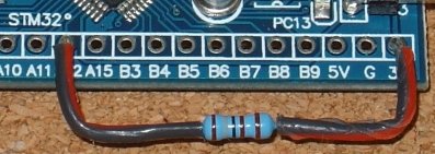
The STM32F103C8 “BluePill” has a common circuit error. The pullup resistor on the USB line running to A12 should be 1K5, but is often 10K on the boards supplied. You can check this by looking at the R10 resistor on the back of the board.

If the R10 marking 103, as shown above, then the board has the incorrect 10K resistor fitted. If it is marked at 152, then the board has the correct 1K5 resistor fitted.
Boards with the incorrect R10 (103) resistor can be fixed by wiring a 1K8 resistor from A12 to 3v3 as shown here.
BEFORE YOU START: Create a restore point on
your PC so that you can undo all the driver/program installs that
STM32CubeProgrammer install and other steps makes. Search “create
a restore point” in the Start menu.
Note: Recovering to a
previous restore point can delete new .ino files you have created so
back them up first
With the ST-Link V2 not plugged in, download and install
the STM32CubeProgrammer.
This installs a number of drivers as well.
Plug in the ST-Link V2
and see its driver installed (after a while)
Open STM32CubeProgrammer. In the Serial number
you will most likely see Old Software
need to upgrade and
an Error old firmware upgrade
message.
Click on the Firmware upgrade button.

Click Refresh
device list and
then Open in update mode.
You may be prompted ST-link
is not in the DFU mode. Please restart it. Remove
and re-insert the ST-Link V2 to restart it.

You can then
click the Upgrade
button.

After the upgrade completes you will see Upgrade successful. Close this window to go back to the STM32CubeProgrammer. Refresh the Serial No to see the upgraded ST-Link serial number. The ST-Link is now ready to use to upload programs.
Recommended: Rename your existing Arduino15 folder, to say Arduino15_org, so that you can go easily swap the STM32 addon in and out of Arduino. The location of the Arduino15 folder is shown at the bottom of the File->Preferences window. Arduino will re-create an empty Arduino15 folder if it is missing.
Install
Arduino IDE and start it. Open the File → Preferences window
and copy this URL (below) into the Additional Boards Manager URL
field (see https://github.com/stm32duino/wiki/wiki/Getting-Started)
https://github.com/stm32duino/BoardManagerFiles/raw/main/package_stmicroelectronics_index.json
Close the Preference window and open
Tools → Board: Arduino Uno → Boards Manager
Choose Type:
contributed and search for STM32 and Click Install for V2.2.0

The STM32_Serial1Passthrough.ino
sketch uses the
millisDelay class to flash the led as data is sent/recieved.
Open
Tools → Manage Libraries and type in safestring to
find the SafeString library (takes a few seconds to search) and
install it.
To program the “BluePill” you need to set it in the Tools Menu
Open the Tools → Board: … and choose the STM32F1 series option

Then for Board part number: select BluePill F103C8

Also select USB
support (if available): "CDC (generic 'Serial' supersede
U(S)ART)" <<<<<<<<<<<<<
very important for the USB to Serial sketch
You
also need to set an Upload
method: which
will be different for each of the three methods below.
The first Arduino IDE programming method uses the STM32CubeProgrammer and the ST-LinkV2 and is the simplest (provided is works!)
Open the Arduino IDE and open the Examples → Basic → Blink sketch.
Carefully set the Tools Menu settings, as described above in Tools
Menu Settings, and then to upload via the STM32CubeProgrammer
and ST-Link V2, choose
STM32CubeProgrammer (SWD) as the Upload
method:

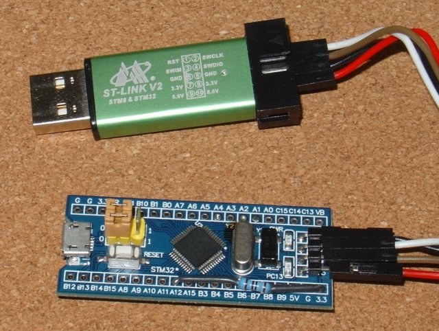
Connect the ST-Link to the “BluePill”
header as follows. (Important: The order of the
ST-LINK V2 GND,SWDIO and SWCLK pins can be different to what is shown
in the photo below. CHECK the order on your ST-LINK V2 clone
carefully)
ST-Link V2 ↔ “BluePill”
SWDCLK
↔ SWCLK
SWDIO ↔ SWO
GND ↔ GND
3.3V ↔ 3V3
Recheck your connections! Note carefully the Red wire goes to 3V3 on both ends and ALL the wires on the ST-Link are connected to the second row of pins.
Note: Boot0 and Boot1 jumpers are both set to the 0 side
Important: The order of the ST-LINK V2
GND,SWDIO and SWCLK pins can be different to what is shown in the
photo above. CHECK the order on your ST-LINK V2 clone carefully
Plug in the ST-Link V2 and click the compile/upload button. The
STM32CubeProg_BlinkUpload.txt
file has a sample Arduino IDE upload output.
The Green led will
start blinking.
You can program the STM32_Serial1Passthrough.ino
the same way. Open a new sketch and replace its code with the
contents of STM32_Serial1Passthrough.ino
and save the sketch as STM32_Serial1Passthrough. Then see Wiring
up the USB to Serial connection
If the upload fails, check that the STM32CubeProgrammer is installed in the 'default' install directory and also see see https://github.com/stm32duino/wiki/wiki/Upload-methods#stm32cubeprogrammer
It can sometimes be convenient to do uploading via the “BluePill” USB connection. This next method installs a HID bootloader into the BluePill and there after programs it via the USB socket.
Connect the ST-Link V2 to the BluePill as shown above in
Programming with STM32CubeProgrammer and ST-Link V2.
Note: Both Boot0 and Boot1 jumpers are set at
0.
Download and unzip
hid_generic_pc13.zip
to get the hid_generic_pc13.bin file. Open
STM32CubeProgrammer and load the hid_generic_pc13.bin,
plug in the ST-Link V2 and download the file into the
“BluePill”
Unplug the ST-Link V2 and remove it from
the “BluePill” header.
Plug in the “BluePill”
USB connection. A USB Input Drive will load (eventually)
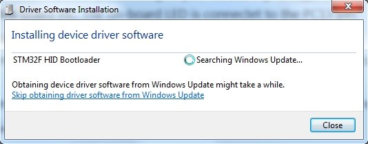

Unplug and
replug in the USB cable. The Green led on the “BluePill”
will come on and stay on.
Open the Arduino IDE and open the Examples → Basic → Blink sketch.
Carefully set
the Tools Menu settings, as described above in Tools
Menu Settings,
and then to upload via the HID bootloader, choose
HID Bootloader
2.2 as the Upload method:

Click the
compile/upload button to program the Blink example. The Green Led
will blink.
You can program the STM32_Serial1Passthrough.ino
the same way. Open a new sketch and replace its code with the
contents of STM32_Serial1Passthrough.ino
and save the sketch as STM32_Serial1Passthrough. Then see Wiring
up the USB to Serial connection
Another alternative programming method, via USB, is to use the Maple bootloader. This need special Maple drivers. The driver install worked will on Windows 7 but may be problematic on other OS's.

Connect the ST-Link to the “BluePill”
header as shown above.
ST-Link V2 ↔ “BluePill”
SWDCLK
↔ SWCLK
SWDIO ↔ SWO
GND ↔ GND
3.3V ↔ 3V3
Recheck your connections! Note carefully the Red wire goes to 3V3 on both ends and ALL the wires on the ST-Link are connected to the second row of pins.
Note: Boot0 jumpers is set to 1 while the Boot1 jumpers is left on the 0 side as shown below

Plug the ST-Link V2 back into the computer. Check is shows up on
the STM32CubeProgrammer. Refresh the Serial No field if
needed.
Download and unzip
generic_boot20_pc13.zip
file and load the
generic_boot20_pc13.bin file.
Open
STM32CubeProgrammer and load the generic_boot20_pc13.bin,
plug in the ST-Link V2 and download the file into the
“BluePill”
Unplug the ST-Link V2 and remove it from
the “BluePill” header. The Maple drivers need to be
installed before plugging in the “BluePill” USB
Move
the Boot0 jumper back to 0
Unplug the ST-Link V2 and remove the wires between the “BluePill” and the ST-Link V2. Set the Boot0 link back to 0
Important: Install the Maple Drivers BEFORE plugging the “BluePill” into the computer for the first time.
Unzip maple_drivers.zip
to a convenient directory. Open a cmd prompt (type cmd into the
Windows Start search) and cd to the drivers/win directory and run
the
install_drivers.bat
That will install
two drivers Maple DFU and Maple Serial.
The plug the “BluePill” into the computer. After a long time the Maple Serial driver will be installed. Ignore the Maple 003 device unplugged msg.

For this programming example using the Maple bootloader, the USB to Serial (115200) converter code will be uploaded. Either of the previous two methods can also be used to create the USB to Serial converter.
Open a new sketch and replace its code with the contents of STM32_Serial1Passthrough.ino and save the sketch as STM32_Serial1Passthrough.
Carefully set
the Tools Menu settings, as described above in Tools
Menu Settings,
and then to upload via the Maple bootloader, choose
Maple DFU
Bootloader 2.0 as the Upload
method:
and
set the Port: to the Maple Serial Com port , e.g. COM44
The Tools menu should look like

Click the Upload button to compile and upload the sketch to the “BluePill”
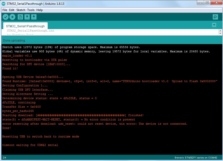
If you get a message (in Red) like
Couldn't find the DFU
device:
Then start the upload again and this
time when the screen shows
Searching for DFU device
Press
the “BluePill” reset pushbutton to get into DFU mode. At
the end of the upload you may see the following error which you
can ignore.
Resetting USB to switch back to runtime
mode
error resetting after download: usb_reset: could not reset
device, win error: The device is not connected.
Once the upload is complete the STM Virtual COM port driver will be installed


The “BluePill” Serial1 Tx pin is A9 and the Rx pin is A10. Solder two male jumper wires into these pins and cut the wires and solder in a 1K resistor in each. These 1K resistors protect against shorting a Tx output to a Tx output and protects against miss-matches in supply volts between the “BluePill” and the target.
You can also power the target from the “BluePill” The 3V3 / Gnd header pins can supply ~250mA
Unplug and re-plug in the “BluePill” to get a USB to Serial converter running at a fixed 115200 baud on the Serial side. Open COM44 in the Arduino Monitor or a terminal program like TeraTerm or CoolTerm The Yellow led (PC13) will flicker whenever data is passing through the “BluePill”

The project covered how to setup Arduino to program the “BluePill” STM32F103C8 using an ST-Link V2, Three methods of programming were described. The STM32CubeProgrammer via ST-Link V2 is the simplest. As an example program a USB to Serial (115200) converter was uploaded. This USB to Serial converter was for use to debug the nRF52832 modules used in the Very Low Power BLE project
AndroidTM is a trademark of Google Inc. For use of the Arduino name see http://arduino.cc/en/Main/FAQ
The General Purpose Android/Arduino Control App.
pfodDevice™ and pfodApp™ are trade marks of Forward Computing and Control Pty. Ltd.

Contact Forward Computing and Control by
©Copyright 1996-2020 Forward Computing and Control Pty. Ltd.
ACN 003 669 994