
|
Home
| pfodApps/pfodDevices
| WebStringTemplates
| Java/J2EE
| Unix
| Torches
| Superannuation
|
| About
Us
|

|
20W Torch
|
by Matthew Ford 8th February 2006
(original 19th November 2005)
© Forward Computing and
Control Pty. Ltd. NSW Australia
All rights reserved.
Introduction, Modifying the standard M*g switch to Momentary Action, Current Limiter, Use and Charging, Costs, Original Direct Drive Circuit, Acknowledgements, Beam Shots, 1XO Lenses
This document describes the mods I did to my Tesla-6 special from Elektro Lumens. The result is a torch which has
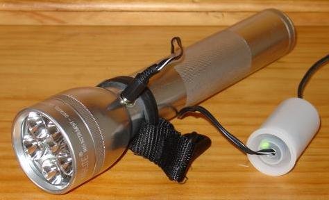
6 x 3W Leds current limited to 2.1A to give
>14W
variable power
rechargeable 6 x AA NiMH via
recharger socket
over discharge protection
either a
momentary on or a two stage switch,
selectable auto off, lock
out
a standard 2D M*g body
an Ultra Clear Lens.
Most of the control features are due to using TaskLED's D2DIM controller driving and my 'high speed' current limiter..
As delivered from Wayne of Elektro Lumens, my special order Tesla6 had 6 x 3W Leds selected to be direct driven by 6xAA NiMH batteries and mounted in the standard 2D M*g head. The leds are wired in 3 sets of 2 leds in series. The M*g switch was delivered in standard condition, un-altered. To mount the recharger socket, Wayne a milled hole in the barrel where the head ends when fully screwed on. Wayne also supplied a deltaV cut off fast charger.
My mod consists of
Modifying the M*g switch to momentary action
Adding a 'high speed' current limiter driven by TaskLED's D2Dim controller. This replaces the first mod which was direct drive via P Channel FET driven by TaskLED's D2DIM controller
Adding a half voltage supply IC (TLE2426) to force the D2DIM controller to shut down when the battery voltage drops below 5.4V (about 0.9V per cell)
Adding short circuit diode protection for the recharger socket with a monitor resistor in parallel
Adding a Nite Ize Lite Ring to protect the recharger socket from water and dirt.
Adding a trickle charger to keep the torch always ready.
Adding an 52.1mm Ultra Clear Lens from Flashlightlens
This description is based on the mod Mag2D LuxIII nFlex mod (8 brightness levels) mod posted by Icarus on CandlePower Forums
Remove the existing switch/bulb holder by pushing it out the back of the barrel. It the switch is tight in the barrel unscrew the switch knob with a small allen key.
Carefully
cut off (I used a hacksaw) the end of the switch. There is a strip
of metal extending into the piece you are cutting off and you may
cut through it without worry. Push the switch out of the holder
towards the top. The nut and metal strip on the bottom of the
switch just comes off. If for some reason it does not use an allen
key to turn the tip of the switch to unscrew the nut at the
bottom.
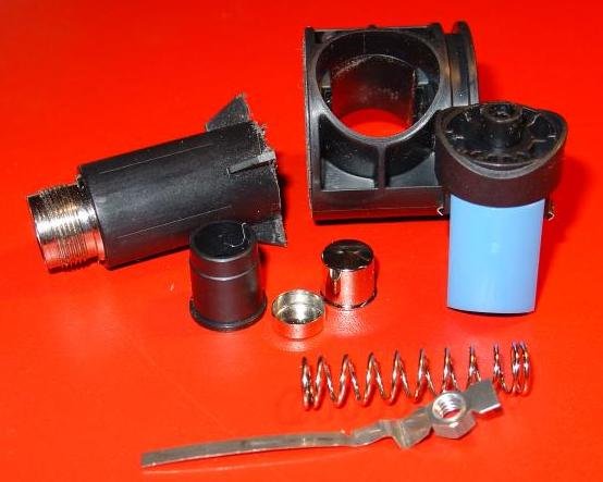
Take
the switch apart. The blue body just pulls off the black head. It
is a press fit of plastic rods in holes.
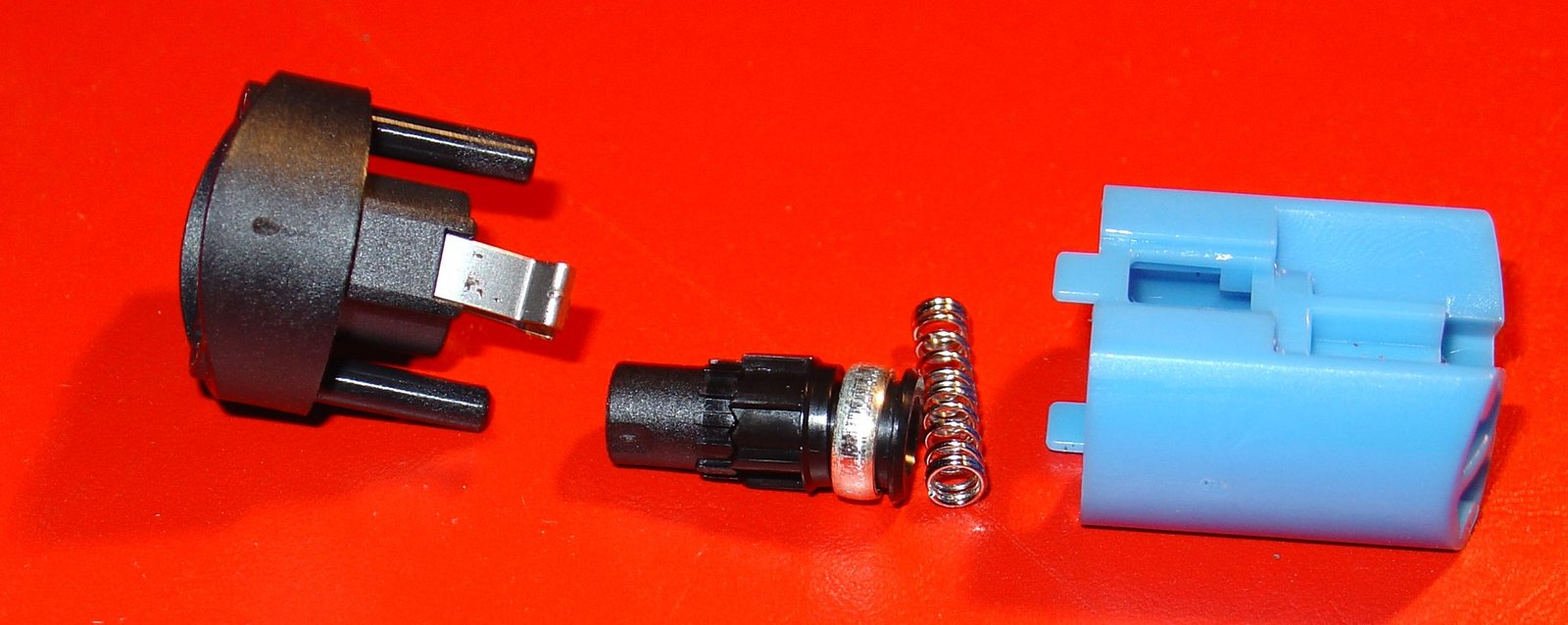
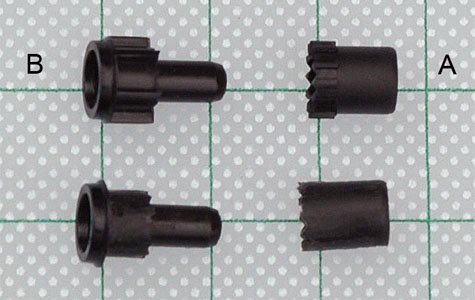
To
make the switch momentary, as is needed for the D2DIM controller,
remove the ridges from part B (see photo below). I clipped them
off with wire cutters. I did not bother to glue the two parts
together as suggested by Icarus and did not clip the serrations on
part A. It seems to work OK without these steps.
This photo is linked from Icarus CandlePower Forums post Mag2D LuxIII nFlex mod (8 brightness levels)
Take
out the metal clips and solder wires to the inside end if each one
to make the new switch connections. Add heat shrink tubing to
cover the contacts.

I
found that it was difficult the get the switch back together with
the heat shrink tubing on, so I removed it from one of the
contacts and cut it back on the other.

The
purpose of the heat shrink tubing is to stop the contact from
touching the metal disk at the back of the positive battery
terminal spring when the switch is re-inserted in the holder. So
you only need the heat shrink tubing on that side.
I pressed out the positive battery terminal and soldered a wire to the spring and drilled a hole in the switch mounting body to pass the wire to the other side of the switch.
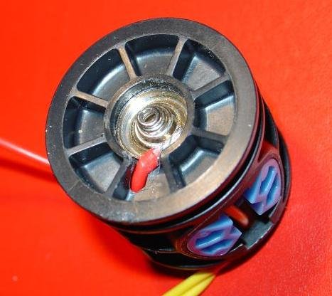

The
two yellow switch wires come out through a hole I drilled on the
back face of the switch mounting body.
I did not put the nut
and screw back in the bottom of the switch assembly. This meant
the switch was sloppy in the barrel until I inserted the battery
holders (2 x 3AA to 1D) and put the tail cap on. Then the switch
was held tightly by the battery holders.
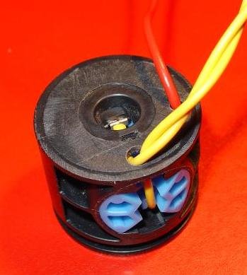
The only problem with the direct drive circuit is that with hot off the charger batteries the Leds draw about 3.5Amps. This drops in the first 5 minutes as the battery voltage get down to its running voltage of about 7.2V. To over come this overdrive, I designed a 'high speed' current limiter. The current limiter needs to be high speed to be able to respond to the PWM output from the D2Dim driver.
The circuit is shown below
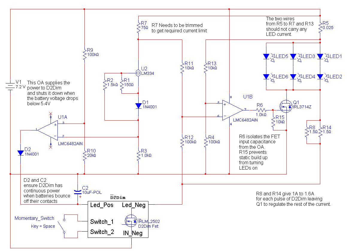
This circuit is a linear buck regulator driven by the PWM output of D2Dim to control the Led's brightness.
Using this current limiter I could limit the total current to the Leds to ~2.1A or about 700mA per led. This level of current improves the efficiency of the Leds and extends the running time. A run time graph is shown below. This shows about 170mins of full brightness followed by 45mins of diminishing brightness. This diminishing brightness is one of the advantages of a buck regulator and gives you plenty of warning that the batteries are running low. Boost regulators usually just run at full brightness until the battery is completely exhausted and then stop suddenly.
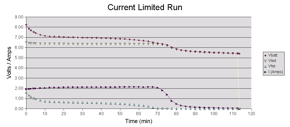
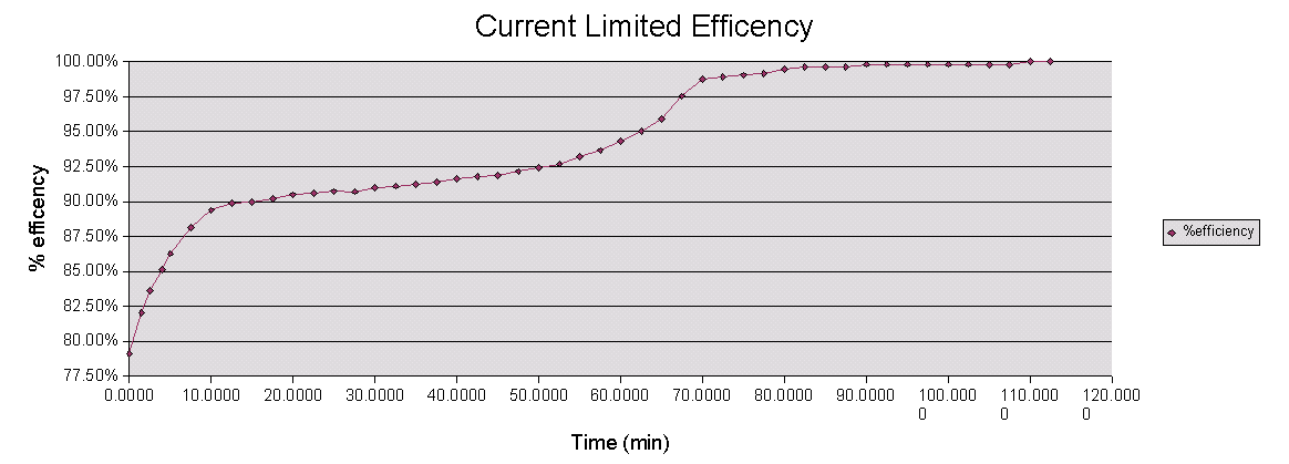
As you can see from the above graph the efficiency of a linear buck regulator is very good if the battery voltage is close to the Led voltage. In this case it averages >91% over the first 70mins and >94% overall.
The circuit was build on the same size veroboard as the original direct drive circuit, except for the Power FET which was bolted to the back of the LED heat sink. To implement this circuit I had to rewire the LEDs to isolate the negative return from the torch case.
The circuit shown above has a number of features.
i) The
current reference voltage is derived from R7 and a constant
current source U2, D1, R1, R2. D1,R1 and R2 provide temperature
compensation. The current source used because it provided better
rejection of supply voltage changes then the available voltage
reference IC I could find.
ii) R3 provides a 0.9V reference
against which a 1/6th of the battery voltage is
compared by U1A. When the battery voltage drops below 5.4V U1A
removes the power from the D2Dim board and shuts down the torch to
protect the batteries. This happens about 45mins after the torch
begins to dim.
iii) The supply to the D2Dim board is fed via a
diode (D2) and a capacitor (C2), these two components ensure the
D2Dim board remains powered even when there is a slight
interrupting to the battery supply. A sharp but gentle knock to
the torch is enough to get the batteries
to bounce off their contacts and momentarily
interrupt the power. In these cases the Leds flash but the D2Dim
board remains powered up and continues to drive the torch. Without
D2 and C2 the torch would be turned off by a gentle sharp
knock.
iv) Although the OA chosen has a high slew rate it was
not quite fast enough to drive the FET and light the Leds when the
D2Dim was set to minimum power. To overcome this I added R8 and
R14 to provide about half the current leaving the power FET to
regulate the remaining current. On the minimum power setting the
FET does not turn on and R8 and R14 provide reduced current to the
Leds.
While the circuit shown above is the one I am currently using.
There are a number of changes I would make if I was doing it
again.
a) I would move the current sense resistor (R5) to
ground side of the circuit. The voltage dividers R11/R12 and
R13/R4 introduce additional inaccuracy in the current setting.
b)
As you can see from the Current graph above the current rises as
the run progresses this is due to temperature compensation of U2
being slightly off, resulting in a rising set point with
temperature.
c) Investigate using a lower power, slower OA to
reduce the power drain when the torch is off. At present it draws
<2mA.
However the problems that would be solved by these changes did not warrant re-wiring the circuit.
George from TaskLED has done a great job of providing full control of all the settings of the torch via the switch. By default the D2DIM as delivered is set to mode 0. In this mode click the switch and the light comes on at full brightness. Press the switch and the light dims. Release the button when it reaches the level you want. Press it again and it brightens. Click to turn the light off. In this mode you have a momentary on function. Press the switch and the light comes on at its last setting. Release the switch and the light goes off.
There is a second mode of operation in which there are 5 set levels of brightness. In this mode clicking the switch turns the light on at the last setting. Pressing and holding the switch switches to full brightness, which is maintained after you release the switch. Pressing and holding the switch again restores the previous light level, giving a two stage switch without going through off. You can adjust the initial brightness in this mode by turning the torch off and then pressing and holding the switch to turn the torch on. The torch turns on a the lowest brightness and then brightens in stages. Pressing and holding again decreases the brightness. Release the switch for a few seconds to lock in the level you have selected.
To lock the torch off, click the switch 3 times quickly. It now takes another 3 quick clicks to turn the torch on.
As well as selecting between these two modes of operation, you can also set an auto turn off feature and force the initial turn on brightness to a particular level. See the D2DIM instruction manual for all the details.
When using the original direct drive circuit, with fully charged batteries the Leds draw over 3A at full power, resulting in more the 20W in the leds. The head gets very hot after about 15mins. Not hot enough to burn you but uncomfortable hot. The torch will run for about 45mins at full power before starting to dim and finally cutting off due to low voltage. The flat discharge curve of the Energizer 2500mAh NiMH batteries means the light output is essentially constant over the 45mins.
The monitor resistor R1 (across D1) allows you to check the battery voltage without taking the batteries out of the torch. Its value is chosen to limit the short circuit current to about 40mA to protect the batteries in the event of a temporary short of the recharging socket. If you don't want to monitor the battery voltage you can remove R1 and get full protection against a continual short of the charging socket.
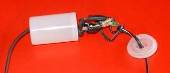
To charge the torch from flat I use the fast charger. If the torch is already nearly fully charged, the fast charger will overheat and destroy the batteries, so I use a trickle charger most of the time to recharge the torch after I have used it for a short time.

The
trickle charger circuit (below) is just a resistor to limit the
charge current. The transistor (BC327) and the 680ohm resistor
detect when there is current flowing to the torch and turn on the
Green Led to indicate charging is in progress.

As
you can see the charger circuit construction is free form in an
35mm film container, with heat shrink tubing to keep things from
touching.
Approximate costs for the components are (as at November 2005 excluding shipping and taxes)
Tesla 6 US$179
Fast Charger US$45
D2DIM US$20
IRF7424
US$4
TLE2426 US$4
6xAA NiMH Energizer 2500mAh US$20
Misc
components Vero Board, resistors, transistor, green led etc
US$30
12V a/c transformer US$15
Nitz Lite Ring US$6
Ultra
Clear Lens US$7
Time 16 manhours $priceless$
Total US$ 330 +
16 manhours
The circuit used in the original direct drive mod was

The
D2DIM controller comes on a small (0.8in diam.) board.
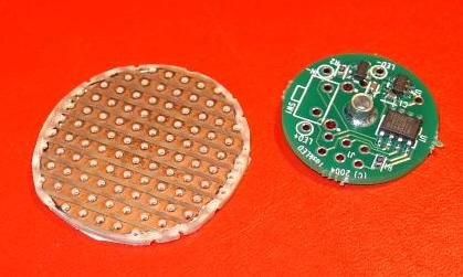
The
P-FET (IRF7424), supply IC (TLE2426) and the pull up resistor R2
are mounted on a small round piece of vero board which also mounts
the D2DIM controller via its connection leads. These two boards
are in turn mounted in the torch via the charging socket and the
diode D1 and monitor resistor R1. The charging socket provides the
earth connection for the circuit board via loop of heavy gauge
solid wire secured around the socket thread. The circuit boards
are suspended in the torch barrel from
this wire plus the diode D1, which also has heavy gauge
leads.
The P-FET (IRF7424) is a surface mount component and very small. I used a magnifying head set to see what I was soldering and some fine gauge resin cored solder and a small wattage, temperature controlled soldering iron. George from TaskLED does this all the time and he uses Kester Organic flux and Kester solder (2331 flux and 331 flux core solder). If you use Kester Organic flux, you have to wash the board since the flux is 'active' and partially conductive. If you use the usual resin cored solder you do not need to wash the board. George uses a circular fluoro based magnifier to 'see' and a Metcal soldering station (not as important as the correct solder and flux). The P-Channel FET was George's idea by the way. Using the TLE2426 to get the correct low voltage cut off was my contribution.

I
actually used two ½ W metal film resistors in parallel for
R1 as these were smaller then the 1W Carbon equivalent.
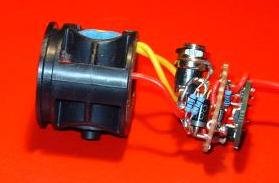
Note
the loop in the red Led supply wire to provide strain relief.
There is a similar loop where the wire attaches to the head

It
takes some 13 full turns to screw the head all the way on, so
start with the head off and un-screw 13 full turns to pre-twist
the red Led supply wire then screw the head on, un-twisting the
wire in the process.
Hint: The -ve return for the leds is via the heat sink screwed against the end of the barrel. As supplied the barrel is lacquered and will not make a connection to the head heat sink. Hence no light. Lightly file the end of the barrel to remove the lacquer and ensure good contact to the heat sink.
Wayne at Elektro Lumens, for making the 'special' Tesla
6
George at TaskLED for his help and advice on applying his
D2DIM board
Icarus from CandlePower Forums for his instructions
on converting the M*g switch to a momentary switch
Al from
CandlePower Forums for his help with some circuit
symbols.
ElectronicsWorkbench (www.electronicsworkbench.com)
for their free circuit drawing tool.
The 5 levels shown here are the 5 fixed levels available in the second mode from the D2DIM board. Level 5 is full power. The torches were 2 meters from the wall and the camera was 4 meters from the wall.
NOTE: All the following beam shows were taken using the original direct drive circuit. The present torch will be a little dimmer because it is current limited to ~2.1A.
|
|
|
|
|
|
|
|
|
Those of you who know the Gerber LX 3.0 will know it has a wide beam spill. The modified Tesla 6 also has a wide beam spill with a bright center spot as shown here.
|
|
|
The above comparison actually looks better in real life because
your eyes adjust to the varying brightness and you see the tree very
clearly in the Tesla 6 spot.
(Camera settings for all pictures ISO
200 F2.8 1/10")
I tried 6 x 1XO lenses from Emilion Workshop. I had to file the ridges a little to get the 6 of them to fit the M*g head. Here are the resulting beam shots.
|
|
|
|
|
|
As you can see the beam shots on the wall look like the 1X0 lens give a tighter spot with less beam spill. However the tree shots show that the 1X0 lenses lose out in spot intensity. I am going back to the standard reflectors.
Contact Forward Computing and Control by
©Copyright 1996-2020 Forward Computing and Control Pty. Ltd.
ACN 003 669 994