
|
Home
| pfodApps/pfodDevices
| WebStringTemplates
| Java/J2EE
| Unix
| Torches
| Superannuation
|
| About
Us
|
|
|
Remote Controlled Light Switch -- Retrofit
|
by Matthew Ford 16th May 2023 (original 22nd
September 2017)
© Forward Computing and Control Pty. Ltd. NSW
Australia
All rights reserved.
Update 16th May 2023 -- This has been superseded by BLE High Power Light Switch, 2023 -- Retrofit, which handles more watts than BLE LED Light Switch and works with Hallway switches.
Update 12th March 2023 -- This has been superseded by BLE LED Light Switch, 2023 -- Retrofit, which handles more watts and uses currently available BLE modules and programmers.
Update 15th November – 2017 Some BLE boards / software stacks deliver the same cmd twice in quick succession. Update to pfodApp V3.322+ and pfodParser V3.17+ to solve this. pfodApp V3.322+ adds a cmd sequence number and pfodParser V3.17+ filters out duplicate cmds
This page covers retro-fittng an existing light
switch with a BLE Remote Control to be controlled from your Android
Mobile, via pfodApp.
No extra wiring is required and
the existing wall switch continues to work.
The
particular example here is for an Australia 240V light switch but the
circuit works just a well for 110VAC with slight change to component
values.
Code is provided for both RedBear BLE Nano (V1.5) and RedBear BLE
Nano V2 to display the control button on pfodApp.
An optional timed Auto Off function is also available in the code.
Note for a High Power version of this project see BLE Power Control with pfodApp. That version can control kilowatts of load.


For all the hipe about Home Automation, current remote control lighting solutions either:- require rewiring to provide a supply power. or need continual battery replacement or they stop working when the existing light switch is turned off.
This solution is Mains Powered but DOES NOT require any extra wiring to be installed. Just install the remote inside the existing light switch using the existing two wires (the Active and the wire back to the light bulb)
Also since this solution is Mains Powered it does not to use batteries. Battery powered BLE sensors that can sleep for most of the time can last for a year before needing a battery change. A light switch remote needs to be active all the time to respond to remote On/Off commands and so will drain the battery much faster. Given the number of light switches in the average house with a battery powered remote, you would be forever changing batteries. Also a battery powered remote would need an accessible battery case for user replacement, so you could not just add the remote behind the existing light switch. Having a Mains Powered remote avoids these problems.
The existing light switch is retained and continues to work. That is you can continue to turn the light on and off from the wall switch as well as being able to turn it on and off from your Android mobile. In particular you can remotely turn the light ON after you used the wall switch to turn it OFF.
Commercial remote controlled light bulbs plug into the existing light socket BUT the wall switch needs to be ON in order to use the remote. If the wall switch if OFF you cannot use the remote to switch the light ON. The circuit used here continues to work when the light is switched OFF at the wall.
The existing wall light switch continues to work even if the remote control circuit fails. If you cannot find your mobile, or if the remote control circuit stops working, you can still use the wall light switch to turn the light ON and OFF.
Once you have a microprocessor controlling your light, you can readily add additional functions. The code below includes an option to turn the light off after a given time. You could also add a light sensor to turn the light on at night and then off after a set time or, if controlling a fan, turn the fan on when the temperature rises.
This diagram is from the Bluetooth V5 “Mesh Profile Specification 1.0”, July 13 th , 2017, Bluetooth SIG

As you can see it consists of a number relay nodes in a mesh. The Relay nodes are active all the time and provide access to other nodes in the mesh and to the battery powered sensors. Installing this Mains Powered BLE Remote module in your light switches will automatically provide a set of nodes across your house that can be added to the mesh as Relay nodes. RedBear BLE Nano V2 is Bluetooth V5 compatible.
However the BLE Mesh specification is very recent and there are currently no example implementations. So setting up the mesh is not covered in this project but once example code becomes available you will be able to re-program you RedBear BLE Nano V2 to provide a meshed Home Automation Network
Here is the basic power circuit for the BLE Remote Controlled Light Switch (click the image below for a larger pdf version)

The BLE module needs very little power (a few mA's). When the light switch is turned OFF, as shown above, a small dribble of current is fed around the switch via the 0.047uF capacitor and 1K resistor. This current flows from the Active, via the capacitor and resistor, through the BLE supply and back to Neutral via the light bulb. This small current, <~5mA, is barely detectable. AC currents less then 5mA are 'safe'. The current is perceptible but does not cause muscle contractions. https://en.wikipedia.org/wiki/Electric_shock
When the light switch is turned on then the full light bulb current flows through the circuit and continues to power the BLE module.
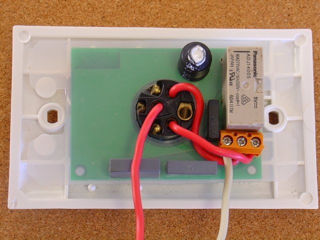
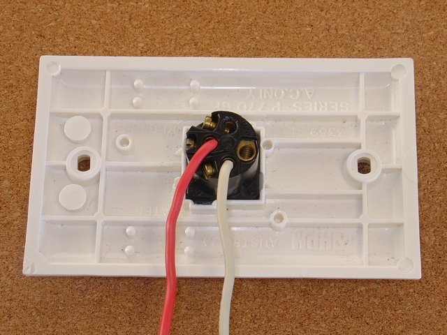
So using only the two existing wires available at the Light Switch, the Active and the 'switch' wire running back to the light bulb, this circuit can be used to power the BLE remote control module. Here are the before and after pictures of the Light Switch and the remote controlled relay. No extra wiring needed.
The remote light switch also requires a 240V relay that requires significant drive current to switch on and off. Here a latching relay is used. A large (1000uF) capacitor, C1, accumulates the small current and provides the 50mA needed to switch the relay.
While this two wire circuit is very convenient for
providing a DC supply for the BLE control module and latching relay,
it does have two limitations.
1) Maximum Wattage Lamp that can be
handled and
2) Current is flowing through the light bulb when the
wall switch if OFF can cause some LED lights to glow or flash on and
off. How to fix this is described below.
Since all the light bulb current has to flow through the zener power supply when the switch if closed (and the light on), the zener has to be handle this current. For a 5W 5.6V zener the maximum theoretical current is 0.9A. In practice to run this zener at 5W requires a large heat sink and your wall switch would be noticeably warm. So I recommend limiting the zener wattage to about 2.5W or about 0.45A. With a 240V mains this limits the lamp to about 100W. For 110V mains the limit is about 50W (say 60W == 0.55A == 3W in the Zener). Given the increasing use of LED lights I think this limitation on Lamp Wattage is acceptable.
BLE Power Control with pfodApp remove this wattage limitation and allows control of kilowatts of load.
If you used, for example, a 3.3V zener then 3W would be about 0.9A or 100W for 110V mains. The problem with this is that 3.3V zeners are not 3.3V when there is only small amount of current flowing through them when the light switch is OFF. Below is a chart of the zener voltage versus current for 5W zeners in the range 3.3V to 10V. The first line on the left is the 3.3V zener. As you can see at low currents (<1A), the zener voltage is nothing like 3.3V.

The 5.1V zener line is marked (5V1). It is much better but still drops to 4V at low currents. Here I have chosen to use a 5.6V zener as a compromise between holding the voltage at low current when the wall switch is OFF and being able to supply the light bulbs load current when the wall switch is ON.
When the light switch is OFF, the 0.047uF capacitor and the 1K resistor allows a small current to flow through the light bulb. Because a capacitor is used to limit the current, almost no 'real' power is used. Real power is only consumed by the 1K resistor and the bridge rectifier and the 5.6V zener. The real power consumed when the wall switch is OFF is about 35mW. The 1K resistor is there to limit the current from higher frequency mains harmonics and power spikes. A transient suppression zener has also been added to the circuit, see the complete circuit below.
For old style filament light bulbs and fluorescent lamps, the small current flowing through the lamp is not detectable. However some 240V LED light bulbs may flash on and off even at this low level of current. Dimmable 240V LED light bulbs may glow.
This does not occur for all LED light bulbs and is unlikely to be a problem in 110V systems. The solution is two fold i) reduce the OFF current, ii) by-pass the current at the light bulb.
i) The OFF current is determined by the mains voltage, the capacitor value and to a much lesser extend the light bulb wattage. Here is a table of AC rms currents for a number of capacitor values. (There is also another ~0.25mA that flows through the switch detector part of the circuit)

The BLE control module uses less then a 1mA (with the Serial disabled), so for 240V 0.033uF is a good starting choice (0.047uF for 110V).
ii) If the light bulb still glows or flashes then you can connect a 100K 1W resistor across the light bulb terminals (in the ceiling). You can connect another 100K 1W resistor in parallel if needed, or try a lower value capacitor. In my case the 0.033uF capacitor and a 100K 1W resistor across the 8W LED dimmable light bulb removed the problem.
This circuit is not suitable for very low wattage LED light bulbs made up of individual LEDs. Even very small currents will cause them to glow.
Below is the wiring diagram for connecting the BLE Remote Control Light Switch to the existing Wall Switch so that both the wall switch and the BLE remote control can operate the light. A pdf version is here.
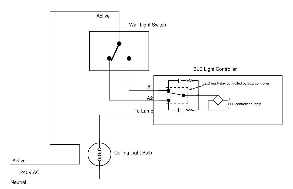
Wall light switches in Australia all come as SPDT (change over) switches so that they can be used as hallway light switches. In the wiring diagram above the existing Wall Light Switch is wired as a hallway switch to the BLE Light Controller that is mounted in the Wall Light Switch.
In the state shown above the ceiling light is OFF and the bottom capacitor/resistor is supplying power to the BLE controller. If you manually switch the wall switch then power flows through the latch relay contact and turns the ceiling light ON. On the other hand if leave the wall switch as it was and remotely trigger the latching relay to change over it will now connect the power from the wall switch to turn the light ON.
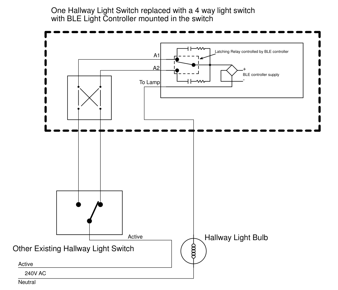
If you retro-fitting the BLE Remote Control Light Switch to one end of an existing pair of hallway switches, you will need to replace that switch with and 'intermediate' or 4 way crossover switch. (That is the same type of switch that you would use if you were adding a third switch to you existing two hallway switches.)
Below is the wiring for retro-fitting a hallway light switch with BLE Remote Control. (A pdf version is here)
Below is the schematic for the BLE Remote Control Light. (A pdf version is here.) The parts list (BLE_Controller_Parts.csv) is here.

The MAX8881 regulator has a 3.3v output, but is primarily used to delay the startup of the RedBear BLE Nano until C1 (1000uF) has charged up sufficiently to supply the 20mA or so of start-up current the BLE Nano needs. R12, R9 and C4 provide the delay by holding the SHDN pin low. This ensures the circuit will start when power is applied even if the switch is open.
Fets U1 and U2 drive the latching relay coils. Their gates are driven by connections to TP3 and TP2. For the RedBear BLE Nano (V1.5), shown in the photos, there are connected to D7 and D5. The RedBear BLE Nano V2 has a different board layout and for that module they are connected to D9 and D8.
Note: On the Nano V1.5, D6 was driven high during power up independent of the sketch code. This connected the relay coil to the 5V supply and prevented C1 from charging up and completing the startup. Using output D5 instead solved the problem.
R1 and R2 provide a power detection circuit. If there is voltage across the switch, i.e. the switch is open / OFF then there is about 0.48V across R2 which is read by the ADC input A5. When the switch is closed / ON the voltage drops to zero. Again a flying lead is used to connect A5 to the BLE module. A5 is used on both V1.5 and V2 Nano's but the A5 pin is in different locations on each Nano.
I used Eagle Cad to layout the PCB. There are few wire links used on the board so that it can be manufactured as a two sided PCB. I supplied a zip of the Gerber files to www.pcbcart.com for the manufacture using 2oz copper. I used gerbv to view and check the Gerber files before submitting for manufacture.
Here is the PCB prior to mounting the BLE Nano module. (Note: D5,D4 tabs are miss-labelled on the screen print)

The bulky components are mounted on the back. A piece of Nylon sheet covers the back and is held in place by the components. This provides insulation for the board which is floating at 240V AC. The 1000uF capacitor, C1, is insulated with shrink wrap and the end of the shrink wrap filled with silicone.

To program the RedBear BLE Nano you need a USB programming board from the BLE Nano V2 Kit. To program the RedBear BLE Nano board wire up VIN, GND, SCLK, SDIO as shown below. Install the Arduino BLE Nano V2 (or V1.5) support. See this tutorial for setting up Arduino for BLE Nano V2 or this one for BLE Nano (V1.5). Then compile and load one of these two sketches depending on the Nano Version you have. For V1.5 use this zip file, BLENanoLightControl.zip For BLE Nano V2 use this zip file, BLENanoV2_LightControl.zip.

Note: Do not power the VDD pin of the BLE Nano module while the module is mounted on the PCB, even if the PCB is not powered. The Nano does not like have volts applied to VDD while VIN is connected to the PCB circuit.
Once the board is programmed you can connect to is using pfodApp. Set up a connection to the BLE Nano as described in pfodAppForAndroidGettingStarted.pdf Then when pfodApp connects to the BLE Nano, your Android mobile will display the button dwg sent by the Nano and allow you to click it to toggle the latching relay.

Note: The first operation of the remote control (after mains AC is applied) will synchronize the latching relay with the On/Off state of the light bulb.
There is a free pfodDesigner
app which allows you to design multi-level menus for pfodApp and then
generates the code for the BLE Nano (see BLE
Nano V2 tutorial), but the code generated by pfodDesigner, while
easier to modify, uses more current (~5.5mA). The code in the
sketches used here has been hand crafted to only run when there is
something to do. The
ble.waitForEvent();
// blocks (sleeps) until something happens, get msg for example
at
the top of the loop() saves power and disabling the Serial UART saves
a bit more.
You can configure you own switch name by editing the
#define DEVICE_NAME "Garage Light"
near the
top of the .ino sketch file.
This sets the name the BLE module will advertise itself as and also sets the name shown below the button on the pfodApp screen.
The sketch also has an Auto Off option which will
turn the light off after a set number of minutes. To enable this
option set a non-zero number of minutes for
const int
OFF_TIMEOUT_IN_MINS = 10; // turn off light in 10 mins
as
delivered the sketch has a 10min time out set. Set this value to 0 to
disable the auto off feature.
The display on your Android Mobile is completely controlled by the code in the BLE Nano. The PushButton.cpp and .h files draw a simple push button that shows the current state of the light On or Off and allows you to press it to send a command to switch it. See this tutorial on creating you own custom controls like this PushButton.
The main menu has a re-request time set to 5secs (5000mS) so that every 5 sec, pfodApp will ask the BLE Nano for an update to show the current state of the light. This allows your mobile's display to be updated with the current state when someone manually operates the wall light switch.
The completed board, with the BLE Nano mounted, is shown here.
Here is the board attached to the light switch
In the installations I have had done so far, there have been no problems fitting the remote controlled switch into the existing space behind the light wall switch.
This project allows existing homes to be easily retrofitted with remote controlled lights. The existing wall switches continue to work even if the remote control circuit should fail. No addition wiring needs to be run and the light can still be remotely turn on after it has been turned off by the wall switch.
Going forward, retrofitting your house light switches with BLE Nano V2 control modules that supports Bluetooth V5 means in the future you can set up a house wide automation network using a Bluetooth V5 Mesh.
AndroidTM is a trademark of Google Inc. For use of the Arduino name see http://arduino.cc/en/Main/FAQ
The General Purpose Android/Arduino Control App.
pfodDevice™ and pfodApp™ are trade marks of Forward Computing and Control Pty. Ltd.

Contact Forward Computing and Control by
©Copyright 1996-2020 Forward Computing and Control Pty. Ltd.
ACN 003 669 994